

Introduction: Remote Controlled Power Strip
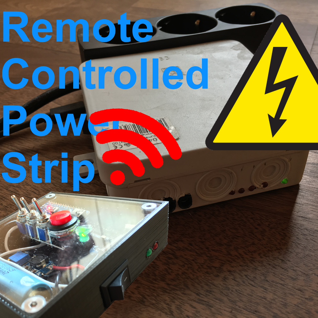


You want to control your power strip wireless, but are bored of modern smarthome accessorys?
You want to have some physical switches and buttons, to control your power strip?
In this Instructable you will learn, how to build your very own Remote Controlled Power Strip, using the 433MHz
HC-12 Transceiver Module!
Step 1: Parts
For building your very own Remote Controlled Power Strip, you will need the following Components:
- Arduino Nano (2x)
- HC-12 Transreciever Module (2x)
- Relay Module
- Toggle Switch (5x)
- Pushbutton
- DC-DC Boost Converter
- Lithium-Ion Battery
- TP4056 Li-Ion Charge Controller
- LEDs
Step 2: Making a Plan
Bevore you start soldering your components together you should make some drafts and test your prototype on a breadboard.
The Idea is, to read the positions of the controllers toggle switches, and send them via the HC-12 Transreciever Module to the Power Strip, where some relays get turned on and off, corrosponding to the switches positons.
Step 3: The Reciever


As a base I chose a Power Strip with three outlets.
The idea is to cut the Leader rail of it and controll each outlet by a 230V relay.
In my build a chinese relay module with 4 relays was used. These take away much work with reversed voltage spikes.
With the three outlets you can control for example:
1.) PC
2.) Sound System
3.) Lights
The fourth relay can be used to trigger your PCs Start / Shutdown switch.
The project is only for demonstrational purposes, i don´t recommed connecting it to mains current, the risk of shock exists!
- Open the powerstrip and cut the leader rail.
- Connect the seperate pieces of the leader rail to the "normally open" contacts of the relays.
- Connect the previous leader wire of the powerstrip to all "inputs" of the relays.
Step 4: The Transmitter


My Goals:
1.) Physical Switches
2.) Portable (Li-Ion Battery)
3.) Fast & Reliable connection
4.) Futuristic design
The brain of the Transmitter is an Arduino Nano. It uses a Serial connection, to transmit commands over the HC-12 Transreciever Module to the Power Strip.
The toggleswitches connect a digital pin of the Arduino to 5V or GND with a 10kOhmes resitor in series.
The pushbutton connects a digital pin of the Arduino to 5V while it is constantly pulled down to GND by a 10kOhmes resistor.
The whole system is powered by a Lithium-Ion Battery.
Because the Li-Ion Battery has a voltage of 3,7V, it is necessary to boost this voltage to 5V by a simple DC-DC Boost Converter.
To charge the Li-Ion Battery i used a simple Charge Module (TP4056).
In order to prevent the Battery from over discharge the voltage is measured by an analog pin of the arduino, that if necessary the system can be set to sleep mode.
As a last step the whole project got fitted into a 3D-Printed enclosure, and a lit of acrylic glass was fixed to it with M4 bolts.
Step 5: Software
My code relates to those Sources:
Dejan Nedelkovski: "Arduino and HC-12 Long Range Wireless Communication Module"
Mark Hughes: "Understanding and Implementing the HC-12 Wireless Transceiver Module"
HC-12 Wireless Serial Port Communication Module User Manual
The standart SoftwareSerial.h library of the Arduino IDE is used to establish a communication between the Arduino and the HC-12.
When two Arduinos communicate over two HC-12 Transreciever Modules with eachother there is nothing different if they would do this by a simple Arduino to Arduino connection throught a wire.
The only difference is that you can adjust the wireless communication by some AT-Settings (For more information read both Tutorials and the User Manual of the HC-12 Module).
Dejan Nedelkovski´s shows in his Tutorial, how to send a command with start (s) and end (e) flag ("s[text]e").
In my build the idea is the same, but the code was optimised a little bit.
Transmitter:
#include
SoftwareSerial HC12(11, 12);
char incomingByte;
String readBuffer;
int HC12_set_pin = 2;
int stat_LED_pin = 10;
int but_pin_1 = 9;
int but_pin_2 = 6;
int but_pin_3 = 7;
int but_pin_4 = 8;
bool but_state_1 = 0;
bool but_state_2 = 0;
bool but_state_3 = 0;
bool but_state_4 = 0;
String string_but_state_1;
String string_but_state_2;
String string_but_state_3;
String string_but_state_4;
unsigned long prev_time;
void setup() {
  pinMode(stat_LED_pin,OUTPUT);
  digitalWrite(stat_LED_pin,LOW);

  pinMode(but_pin_1,INPUT);
  pinMode(but_pin_2,INPUT);
  pinMode(but_pin_3,INPUT);
  pinMode(but_pin_4,INPUT);

  HC12.begin(9600);
  pinMode(HC12_set_pin,OUTPUT);
  digitalWrite(HC12_set_pin,HIGH);
  delay(5);
  digitalWrite(HC12_set_pin,LOW);
  HC12.print("AT+DEFAULT");
  HC12.print("AT+B38400");          //Setting Baudrate to 38400bps
  digitalWrite(HC12_set_pin,HIGH);
  HC12.begin(38400);
}
void loop() {
//Checking Battery voltage
if((analogRead(A7)/204.8) > 3.6){
//Reading Button States
but_state_1 = digitalRead(but_pin_1);
but_state_2 = digitalRead(but_pin_2);
but_state_3 = digitalRead(but_pin_3);
but_state_4 = digitalRead(but_pin_4);
//Converting into String for Serial communication
string_but_state_1 = String(but_state_1);
string_but_state_2 = String(but_state_2);
string_but_state_3 = String(but_state_3);
string_but_state_4 = String(but_state_4);
//Sending Button State Strings with start and end flag
HC12.print("s" + string_but_state_1 + string_but_state_2 + string_but_state_3 + string_but_state_4 + "e"); //Waiting for Answer of reciever
prev_time = millis();
readBuffer = "";
while( HC12.available() == 0 && (millis() - prev_time < 50)) {};
if(HC12.available() && HC12.read() == 's') {
do {
while( HC12.available() == 0 ) {};
incomingByte = HC12.read();
if( incomingByte == 'e' ) break;
readBuffer += incomingByte;
} while( true );
} //If Answer of reciever is correct, light up status LED
if(readBuffer == "OK") {
digitalWrite(stat_LED_pin,HIGH);
}
else{
digitalWrite(stat_LED_pin,LOW);
}
delay(5);
}
//Blink status LED, if Battery voltage is low
else{
digitalWrite(stat_LED_pin,HIGH);
digitalWrite(13,HIGH);
delay(100);
digitalWrite(stat_LED_pin,LOW);
digitalWrite(13,LOW);
delay(400);
}
}
Reciever:
#include
SoftwareSerial HC12(10, 11);
char incomingByte;
String readBuffer;
int HC12_set_pin = 2;
int r1_pin = 9;
int r2_pin = 8;
int r3_pin = 7;
int r4_pin = 6;
bool r1_state = 1;
bool r2_state = 1;
bool r3_state = 1;
bool r4_state = 1;
void setup() {
  pinMode(r1_pin,OUTPUT);
  pinMode(r2_pin,OUTPUT);
  pinMode(r3_pin,OUTPUT);
  pinMode(r4_pin,OUTPUT);

  digitalWrite(r1_pin,HIGH);
  digitalWrite(r2_pin,HIGH);
  digitalWrite(r3_pin,HIGH);
  digitalWrite(r4_pin,HIGH);
HC12.begin(9600);
pinMode(HC12_set_pin,OUTPUT);
digitalWrite(HC12_set_pin,HIGH);
delay(5);
digitalWrite(HC12_set_pin,LOW);
HC12.print("AT+DEFAULT");
HC12.print("AT+B38400"); //Setting Baudrate to 38400bps
digitalWrite(HC12_set_pin,HIGH);
HC12.begin(38400);
}void loop() { //Waiting for start flag
if(HC12.available() && HC12.read() == 's') {
readBuffer = ""; do {
while( HC12.available() == 0 ) {};
incomingByte = HC12.read();
if( incomingByte == 'e' ) break;
readBuffer += incomingByte;
} while( true );
//Converting message of Transmitter into ON or OFF states for the separate relays
r1_state = (1+(int)readBuffer.charAt(0) - 49);
r2_state = ((int)readBuffer.charAt(1) - 48);
r3_state = ((int)readBuffer.charAt(2) - 48);
r4_state = ((int)readBuffer.charAt(3) - 48);
//Sending Answer
HC12.print("sOKe"); // Set relays (if relay pin is low, the relay establishes a connection
digitalWrite(r1_pin, (invert(r1_state)));
digitalWrite(r2_pin, (invert(r2_state)));
digitalWrite(r3_pin, (invert(r3_state)));
digitalWrite(r4_pin, (invert(r4_state)));
}
}
//Inverting function (makes LOW to HIGH / HIGH to LOW)
int invert(int in){
int out;
if (in == 0){
out = 1;
}
if (in == 1){
out = 0;
}
return out;
}
Step 6:
Although you should not try this at home, i hope could get some inspiration for your next project by this instructable!
For questions or improvements, send me a message or leave a comment.
Jens_R


