

Introduction: Simon Says With LEDs and Sound


Hello and welcome back to Instructables!
Many of us have all played Simon Says where inevitably you find yourself hopping around on one foot while making elephant noises and you wonder to yourself why it was ever a good idea to say "yeah, I'll come play".
But perhaps while you could do without the mild amount of embarrassment, you still find yourself wishing you could play a game of Simon Says a little more often, even if it was just in the form of a microcontroller project.
If so, you're in luck! This project takes the classic Simon Says game and implements it with both LEDs, sound effects, as well as a pair of different game modes.
Step 1: Why Should I Read This?
Great question!
After all, it would be equally viable to read a different Instructable on creating a Simon Says game and one on creating sounds with a microcontroller (like these Instructables here and here) and combine your garnered knowledge from both of those to re-create this Instructable. In fact, I think it would be awesome if some people did that -- to me that's part of being an engineer; taking two separate but distinct ideas and combining them to create something you haven't seen or done before.
But for those of us (such as myself) who either like a little more guidance or some affirmation that what they are attempting to do is correct, we have this instructable to help walk through some of the finer points.
Step 2: Materials That I Used

As always, before a project can be completed, one needs to make sure that they have everything they need on hand. I personally used a number of products from Digilent since I had those on hand and I really like that their Pmods are compact so that minimal wiring is required on my part to get access to all of the functionality, whether it's multiple switches, a 12 bit DAC, or an audio amplifier.
But here's what I used:
a chipKIT WF32 - a PIC32 microcontroller to process user answers and act as "Simon"
a PmodDA4 - an 8-channel 12-bit Digital-to-Analog converter to light up each LED without using a bunch of I/O pins
a pair of PmodSWTs - 4 slide switches to light up LEDs in the pattern you think you saw
a PmodAMP2 - an audio amplifier that can accept an analog signal or a PWM audio signal
9 LEDs - 4 red, 4 green and a yellow LED for visual appeal
a push button - to submit a final answer
a breadboard - to put all of the components on
wires - to route both power and digital signals either in the form of jumper wires or 6-pin Pmod cables
a standard pair of earbuds or a speaker - so you can actually hear the sound
Note that if you check out the video at the end of this Instructable before the end of February, you may find a helpful way to help purchase some of these components ;)
Step 3: Setting Up the Circuit


Let's go ahead and get started!
If you haven't done so already, go ahead and start the download the Arduino IDE and the chipKIT Core so that we can program our board. Instructions on how to do that are available here.
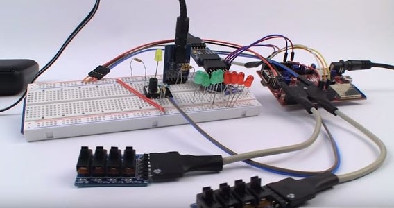
Once that has been started (or if you already have them both downloaded), we can go ahead and get our circuit set up. I imagine that you all are clever people, so what I will do is provide images of the project as well as a list of I/O pin connections that I used in my project.
Attachments

Step 4: What Each Component Does


The Simon Says game consists of several different components that are, in essence, what makes this game work: the two sets of PmodSWTs and the final answer button, the PmodDA4 and the LEDs, the PmodAMP2, and the WF32 hosting all of the code.
The switches can be turned on one at a time to match the LED flash pattern that was presented by "Simon", with the WF32 keeping track all of the switches that have been flipped. Once you think that you have matched the given pattern, you can press the final answer button (the one in the middle of the breadboard), informing the WF32 to compare your pattern with Simon's pattern. You can learn more about how the game portion of my Simon Says game is set up codewise (although it's not exactly the same code for this particular setup with the sound and PmodDA4) here.
If the two patterns match, the WF32 informs tells the PmodDA4 over the SPI communication protocol (more information on communicating to it over SPI here) to flash all of the green LEDs. If the patterns don't match then the red LEDs are flashed instead. Similarly, every time a switch is flipped, the WF32 tells the PmodDA4 to enable the correct output channel turning on the LED and then tells the PmodDA4 to disable that channel when the switch is turned off.
The PmodAMP2 receives a pulse width modulated signal that represents a music note whenever an LED is switched on. Additionally, victory music or depressing music is played every time you successfully or unsuccessfully guess the pattern, respectively. More details on creating sounds with a microcontroller can be found here.
Step 5: Code Changes

I mentioned on the previous step that some of the code has changed from the previous Simon Says Instructable. (The new code is available in a text file, MPIDE, and Arduino file) Most of these changes do not change the user experiences, e.g. assigning each switch to the visually appropriate LED, or getting the PmodDA4 to light up the LEDs instead of a shift register.
There are two changes though that do affect the user experience though: incorporating the sound for the PmodAMP2 and the addition of hard and easy mode. The PmodAMP2 is able to accept a PWM or an analog signal to produce sound that can be "tapped into" through its standard sized headphone jack.
For this project, I sent square waves representing various music notes (the C major scale) for each of the eight LEDs whenever one was lit up, either by Simon or the user. Additionally, if the user successfully guessed a pattern, a victory sound (reminiscent of one finding a heart container) is played while the green LEDs are flashing. If the guess was incorrect, a sad wah, wah, wah, wahwahwahwah sound is played instead.
As I mentioned earlier, the other additional piece of code is the hard and easy modes. The WF32 microcontroller chooses the appropriate game mode when it first boots up based on the logic level detected at one of its I/O pins. If pin 39 is found to be at a logic level low, hard mode is chosen where the pattern is different for every single guess whether the user guessed correctly or not.
On the other hand, if a high logic level was detected on pin 39 during start-up, the game begins in easy mode. This time, the pattern will be maintained for each correct guess, so you might end up getting an LED pattern in the form of 2;
2, 5;
2, 5, 1;
2, 5, 1, 8;
and so on. If you ever guess the pattern wrong though (for both easy and hard mode) the pattern length resets to a size of just one LED flash.
Step 6: Parting Thoughts
Check out the YouTube video of the Simon Says game in action!
If you have any questions, comments, (or even concerns), feel free to post them in the comments below and I'll do my best to help address them!

Participated in the
Full Spectrum Laser Contest 2016

Participated in the
Digital Life 101 Challenge


![Tim's Mechanical Spider Leg [LU9685-20CU]](https://content.instructables.com/FFB/5R4I/LVKZ6G6R/FFB5R4ILVKZ6G6R.png?auto=webp&crop=1.2%3A1&frame=1&width=306)


