

Introduction: 3D-RC | Arduino Based RC Car


This is a beta version of the manual, it may contain some unsaid information, so feel free to ask if you don't understand something
Supplies
3D models:
https://makerworld.com/en/models/1153631-3d-rc-arduino-based-rc-car#profileId-1158230
https://www.printables.com/model/1191309-3d-rc-arduino-based-rc-car
Attachments

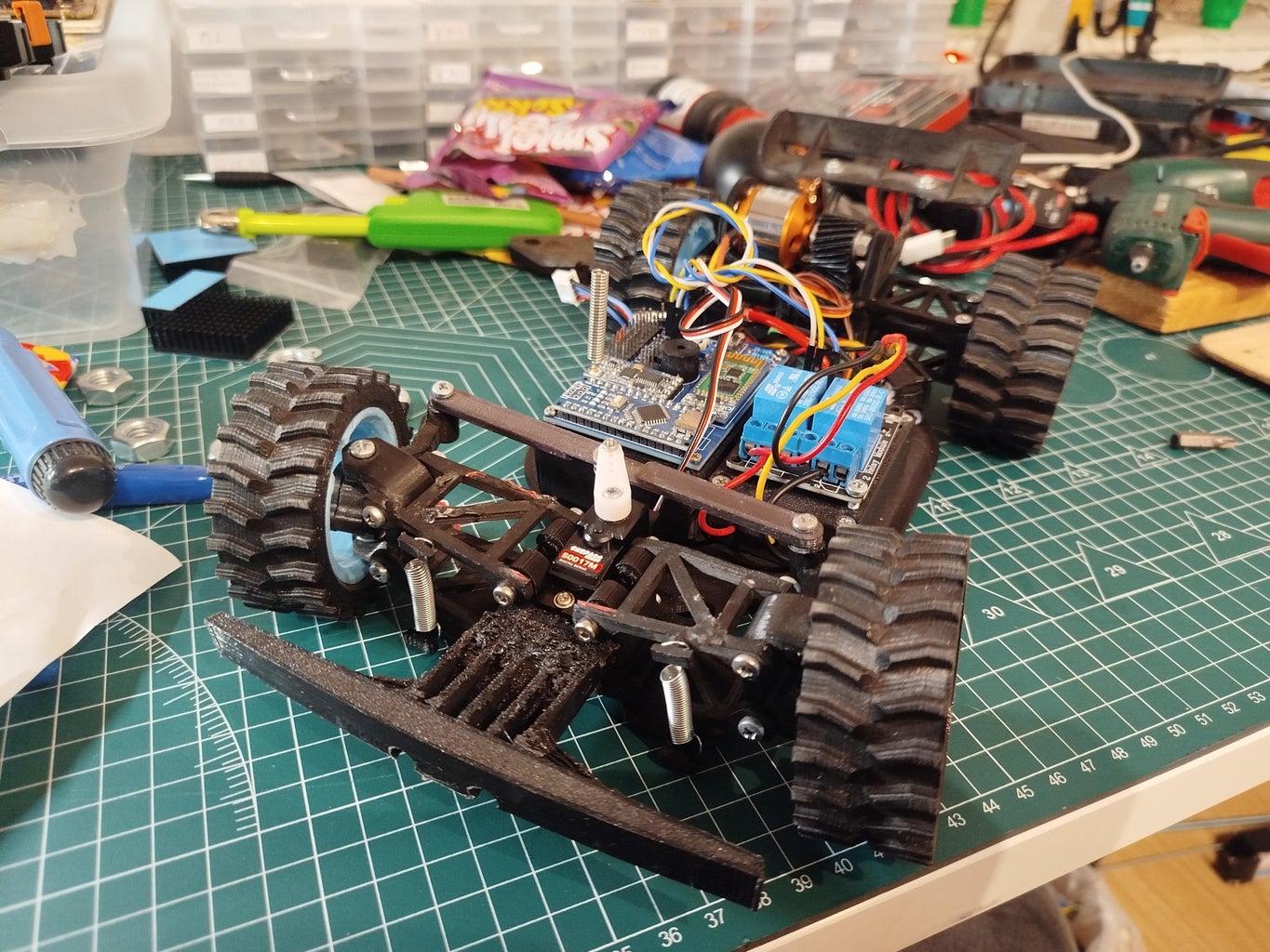
Step 1: Chasis

We will start with the chassis, print them with strong material (preferably ABS/ASA, but Pla can also do it) 70% infill, 7 walls, 4 layers base and top.
Then add all 8 inserts.
Step 2: Suspension


Now the suspension, screw the front first, then attach the back.
Finally, you can add springs/rubbers as suspension.
rear_assembly: all pages (make first)
front_assembly: page 7-10

Step 3: Electronics Mount


Now we will mount the electronics, screw the battery and ESC holder with the help of M3x6.
Remove the protective film from ESC (I recommend mounting the heat sinks), then attach the upper part of the ESC housing and tighten the relay.
Connecting the cables according to the scheme (I soldered them to the relay plate from the bottom)
Step 4: Battery


Put the battery, make sure that all wires protrude from the housing, and the battery does not fly loosely in the housing.
If it is too loose, you can add foam/cardboard on the sides and from above
Step 5: PCB
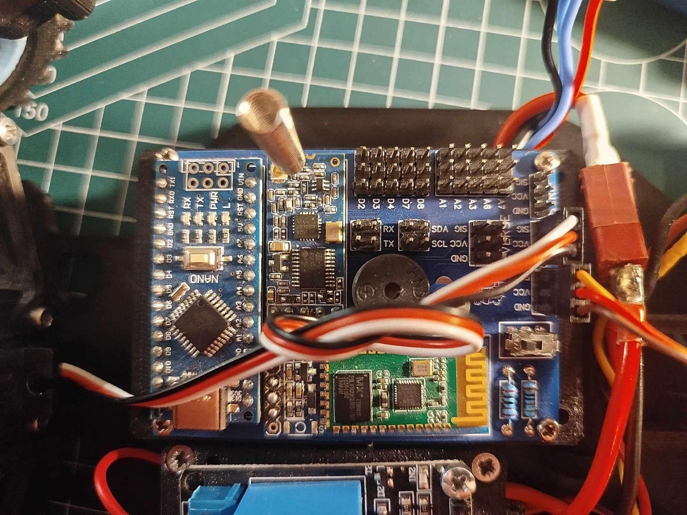


Now screw the PCB, make sure you don't get into the battery,
Upload the Arduino code.
Attachments
Step 6: Connect All Wires


Now connect all electronics, use this scheme:
ESC 3wire cable -> ESC pin (orange/white wire = SIG)
SERVO -> SERVO pin (orange/white wire = SIG)
RELAY VCC -> REVERSE VCC pin
RELAY GND -> REVERSE GND pin
RELAY IN1 + IN2 -> REVERSE SIG pin
[optional] RGB STRIP -> STRIP pin (orange/white wire = SIG)
[optional] rear LED's -> REVERSE pin's (VCC -> 1k resistor -> +led, GND -> -led, SIG -> 5k resistor -> brake led)
[optional] front LED's -> sorry, forgot (im gonna find out later)
Step 7: Stering Link


Turn on the car, after a while the servo should be stuck in a neutral position, set the offset potentiometer to the center, and with the voltage turned on, screw the last link
Step 8: Transmitter

For control we will use a phone with bluetooth, install the "RoboRemo" app (free one will be good) and follow the instructions:
~UI installation:
menu -> interface -> import -> select "transmitter_ui.interface"
~Car connection
menu -> connect -> Bluetooth (RFCOMM) -> HC-06
You can find the file only on printables (link at the beginning), instructables does not support this extension, and printables does not fully support it either, so don't forget to unzip the file
Step 9: Finish


And thats all! Your car is ready to drive, don't forget to leave your rating and share photos!
