Introduction: 5x5x5 LED Cube (Arduino)

Hi all... This is my first Ible so first-off I will appologise if I have missed anything out.
Secondly, My project is based on AJMontag's 'LED Cube with Arduino and custom PCB' found here https://www.instructables.com/id/LED-Cube-with-Ardu... Without this project, I would never have attempted mine so all credit goes to him :)
I decided to document my construction process as I was making my own PCB instead of having one professionally built which was slightly harder than expected but overall the results are great.
As with any soldering, don't touch the iron when it is turned on, etc. (insert common sense here)
Step 1: Parts...
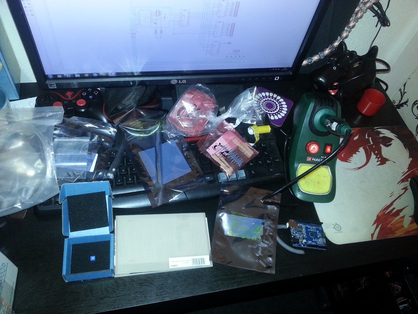
Right... First off you will need the parts which I sourced from Farnell, ebay and my local random tat shop...
74HC238 3-8 Decoder X5
LED 5mm Diffused Blue LED X125
RES 150 Ohm Resistor X30
2N4401 NPN Transistor X5
POT 10k Ohm Trim-Pot X1
PCB Board X1
Pins Pin strip for jumpers
IC Socket 16 pin socket for 74HC238 X5
Arduino Uno
Thick Wire
Male and Female spade conectors
IDE Socket and cable
Heatshrink Tubing
Dip switch or jumpers
Step 2: Starting the Project...


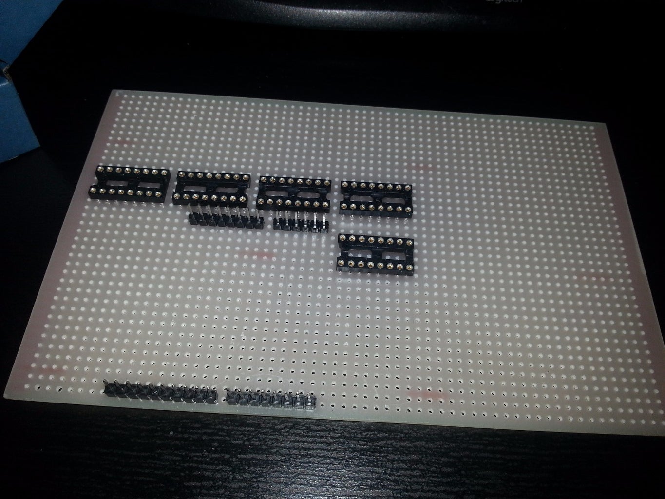

First off I started by working out where the Arduino was going to sit on the board and started attaching the IC Sockets. The layout images once again are what I used from AJMontag's cube so hats off to him for the design!
I have also included the Eagle files from the original project.

Step 3: Building the Board...
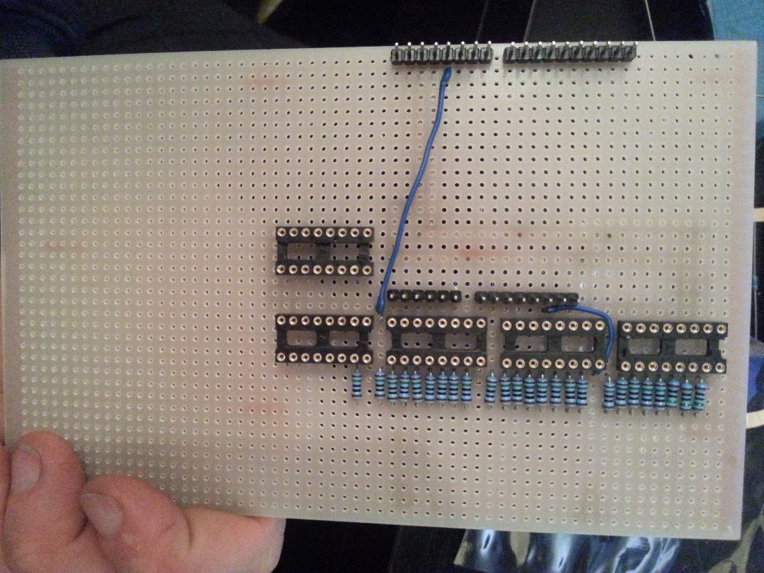


After the IC sockets were attached, I added the resistors and then the IDE socket.. I decided to use this approach as I did not want the cube on my board but wanted to have my board hidden inside a box with the cube on top.
The IDE cable and socket give you 40 pins to play with and we need 25 for the columns and 5 for the planes so it seemed the perfect option to me.
Once the resistors were fitted I added the DIP switch, the reset jumper, the POT and the 2N4401 Transistors.
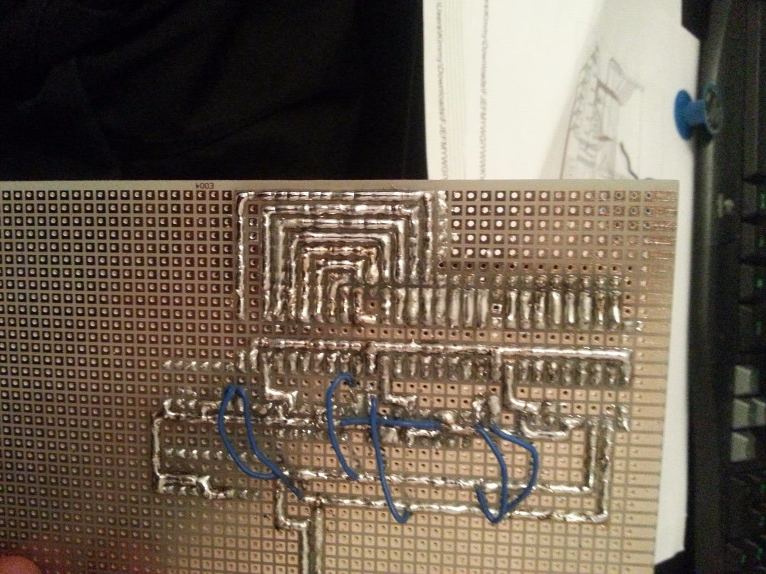
As you can see, it involved a LOT of soldering so I can see the advantage of a pre-fabricated PCB... I also ran into an issue with the fact the original I was working from was double sided and I didn't have a double sided PCB to work with so I needed to add a lot of wires to join things up.
Once all the soldering was up I fitted the 74HC238N chips into the holders and fitted the Arduino.
Step 4: Building the Cube...
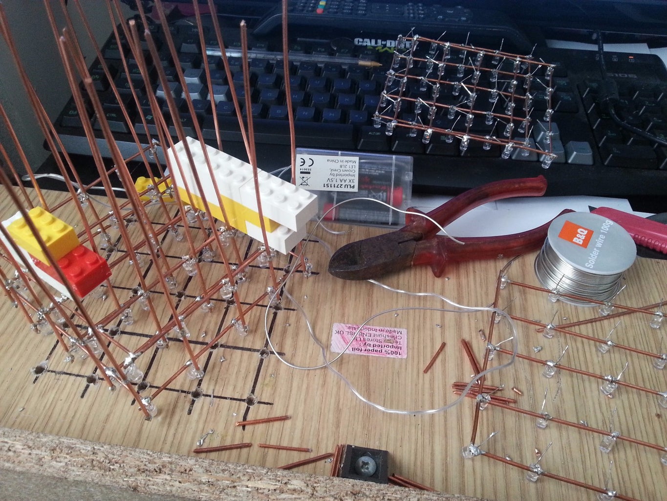

This bit took me a while... when I say a while, I mean it took AGES to get everything soldered together...
I started off making a template by marking out and drilling holes into a piece of wood and placed the LED's into the holes... I then soldered the 25 LED's to the 7 copper bars. (which I made from using the copper wire from inside some twin and earth electrical cable I had in my shed... )
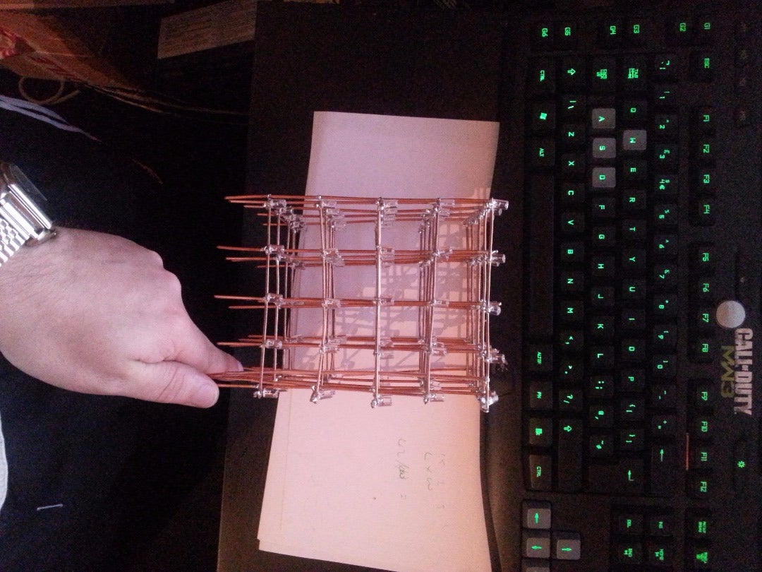
Once all 5 planes were made I joined them together and checked each bulb worked by using a battery pack shorted across each plane and column in turn.
Each plane has a connecting rod and I placed heat-shrink tubing over them to stop them earthing on the lower planes.
Video of the planes getting checked to make sure the bulbs and circuit worked here https://www.facebook.com/craig.horner.585/videos/10153016567107695/
Step 5: The Box...


I found a basic box in a local tat shop (I think it was Pound Stretcher) and cut holes in it for the power and USB cables.
Step 6: Mounting the Cube...
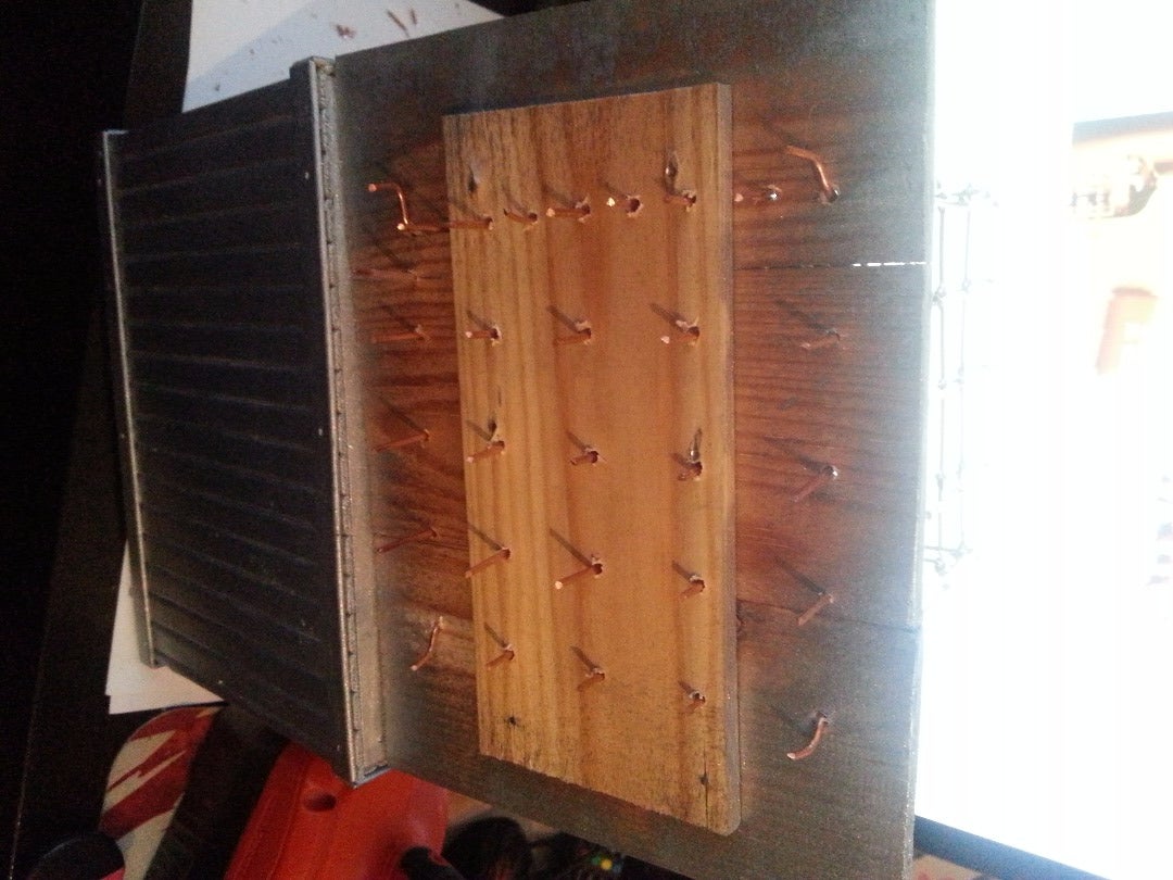


I drilled holes in the lid and mounted the legs of the cube through them... the 4 corner legs were bent slightly to hold the cube in place.
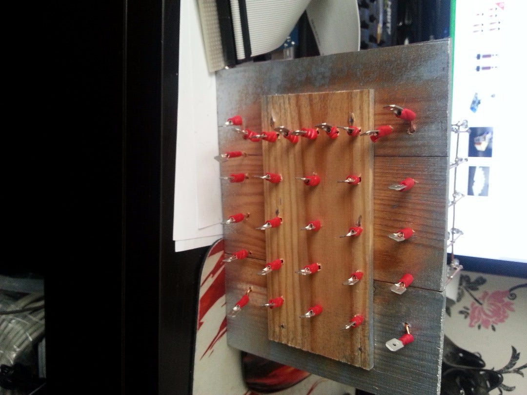
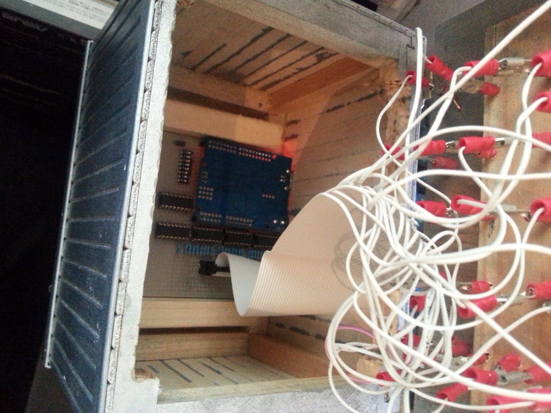
I then fitted male spade connectors to each copper leg and fitted female connectors to the 30 pins on the IDE cable.
I connected it all together and placed the board in it's place in the bottom of the box.
Step 7: Programming...
Once it is all together you are ready to upload the code... there are 4 programs that are chosen by the position of the POT... If the POT is turned all the way clockwise you will get program 4, a quarter turn anti-clockwise will give you program 3, etc...
The DIP switches don't seem to do anything but they were in the original design so I included them in mine and left them all turned on in-case they were important.
I know nothing about writing the programs so I once again used the program provided with the original instructable but it all worked a treat.
I hope I have not missed anything out and I also hope this has been informative and shows a different option to getting a board manufactured.
This project has cost roughly £40-£50 in total... I know I could have probably bought a kit from eBay but where would the fun have been with that? :D
Video of it working in the dark here... https://www.facebook.com/craig.horner.585/videos/10153172940072695/