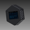
Introduction: AirMonitor
Hello Internet!
For some time now I've sourced various sensors from our favourite auction website for pennies with last minute bids. By getting my hands on a Linkit ONE I decided it's time to put all these together in a nice tidy box and make it portable with it's battery. I wanted to be able to measure ALL the following at the same time with ONE device:
- Ambient temperature
- Relative humidity
- Dust concentration
- CO2/CO (Carbon products)
- Toxic substances like butane, gaz, lpg and smoke
All these values should be displayed simultaneously in ONE screen. So I decided to try these cool looking OLED displays. Got a tiny 0.96" to start with.
So lets start!
Parts List:
- Linkit ONE
- OLED 0.96 display
- Interface: I2C
- Voltage: 5V
- Dust sensor
- Interface: PWN
- Voltage: 5V
- DHT11
- Voltage: 5V
- MQ-7 Carbon Monoxide CO Gas Sensor
- Interface: Analog
- Voltage: 5V
- MQ-2 Methane, Butane, LPG and smoke Sensor
- Interface: Analog
- Voltage: 5V
Step 1: Code
I assume you have already setup your PC for Linkit to work with Arduino IDE. If not try this first.
Load the attached AirMonitor file to your Linkit ONE
Make sure it uploads with no errors!
As every developer believes my code is self-explanatory :)
I have a few comments here and there but:
- At the beginning I define the pins of the various sensors. If you want to change them, change them there
- Some sensors (i.e. dust) need a warming up period, so the display starts with a "Initialising display..." message for a couple of seconds
- Temperature is hard coded to Celsius. To use Fahrenheit use the ready converted tempraturef variable
- The function display.drawPixel as you can guess, draws 1 pixel in a specific location. I use that function many times to draw the micro symbol (μ - greek mew)
Attachments
Step 2: Wiring
No it's time to connect all these little guys together.
As you may have already noticed I have specifically chosen only components that work with 5V so that I have ONE single power line @ 5V instead of running 3.3V, 5V and 12V. This simplifies so much the wiring.
See attached Linkit pinout and connect 5V (labeled Vcc) and ground (labeled GND) to all other 5 components (display, dust, CO2, toxic, dht11). Then connect the signal lines as below:
- Display
- SDA to Linkit SDA
- SCL to Linkit SCL
- Dust sensor
- Data pin to Linkit D9 (PWM)
- CO2 sensor
- Data pin to Linkit A2 (Analog)
- Toxic gaz sensor
- Data pin to Linkit A1 (Analog)
- DHT11 sensor
- Data pin to Linkit D10 (Digital)
Thats it! Put everything in a box making sure you leave plenty of gaps for the air to come in. See photos
Step 3: Optional Improvements
- Battery
- As I realised the Linkit internal battery couldn't give me enough juice so I had to use a standard power bank I had lying around. You can either use the power bank with a MicroUSB cable to run Linkit or integrate the battery/charging circuit in your box. That's what I have done (see images).
- Plot
- As you already have the OLED display its super easy to actually plot the live data as they get collected
- Log
- As you already have an SD card it would be cool to save all data on the SD. So you can take the AirMonitor with you for a drive around town, at work or hiking and later when you get home investigate the quality of the air you breathe. With the integrated GPS functionality it would be very simple to plot all measured dimensions with different colours against X-Y coordinates and plot them on Google maps (kml)
- [Your idea here]
- Send me what else you want added and I will try to help you as much as I can


