Arduino Chicken Coop Controller


Intro: Arduino Chicken Coop Controller
Over the last few years my family has been keeping ex-battery hens - they are about 18 months old and have lived their entire lives within a caged environment. As much as we love these little bundles of joys and eggs it can be a drudge getting up in the early morning letting them out to roam the garden because the sun is up and bright at 5.00am!!
It would be great if we could have an automated door that could open just after sun rise and close half an hour after sunset where hopefully they are all cosying up to each other in the coop. Sadly there have been times we have forgotten to lock them safely away and discover the horrible consequences when a fox has attacked and killed some of them.
This instructable brings together a number of ideas I have seen on the web to create an Arduino Chicken Coop Controller (ACCC) to automate a chicken coop door and where possible I will give direct credit to those people designs/code I have adapted to create this personal sleep saving device. Many thanks to those who have shared their great ideas which has spawned this device.
The main features of the ACCC:
- Based on the Arduino architecture for easy prototyping and adaptation to your coop requirements
- Uses common parts easily found at you local DIY/hardware store/shop such as cheap electric screw drivers
- Uses a real time clock to maintain time even when the device is temporary disconnected from power
- Adjusts the opening and closing times of the door according to the current month - you can set it to your own timezones
- Provides a manual override just in case one of your lovely darlings misses sunset!
- Provides a min and max temperature reading inside the coop from midnight so you can keep an eye on your brood's welll-being
- A display which can be switched on and off to read out the current ACCC status and will not disturb your feathered friends sleep at night
Most of the electronic components were sourced from eBay and I estimate the whole device excluding the wood was under £30
STEP 1: Building the Door

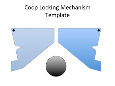
Clint didn't actually provide the plans on his YouTube link so I set about to recreate them and I have attached a PDF file which you can scale to your needs. I hope from the series of pictures and my video file you can see how the door assembles and works.
Some pointers:
- I would advise using the acrylic sheet facing plate rather than plywood as it provides a frictionless face for the pieces to move freely
- You really need to see it moving to make sure it works freely and you know where to make any tweaks
- It really looks cool and you should show off your handy work
Use brass screws/stainless steel bolts where possible and treat the ply with a suitable wood preserve - I wouldn't use a vanish as this might over time cause the workings to foul. When fixing the perspex cover use brass screw cups to spread the load and will hopefully stop the cover from shattering.
I found loosely fitting the door lock levers ensured they worked even if they were damp from the outside weather. I made two doors to test. One has been in manual use to see how it would stand the damp and cold english weather - which it did! So hats off to you Clint it is a very practical design.
I have taken loads of pictures so you can see from all angles the design and how it is constructed and assembled. I haven't commented on every picture as I think it is reasonably self explanatory - well I hope!
STEP 2: Motor Assembly
I wanted to source a motor and gear assembly that was under £10-15 which isn't easy. I came across a cheap electric screw driver for less than £6 and when I stripped it discovered I had all the components I needed. Including a:
- 3.5v-4.5v Motor which could be hot wired to a chunky 6v battery
- planetary plastic gear box which was going to provide enough torc to raise the plywood door
- chuck and screw driver bit to attached a wooden real pulling the door opening cord
- rechargeable battery pack to test the door assembly
- plug transformer to trickle charge the motor battery - eventually substituted it for a 9 volt plug PSU so I could trickle charge the 6 volt lead acid battery and the 5 volt arduino regulator.
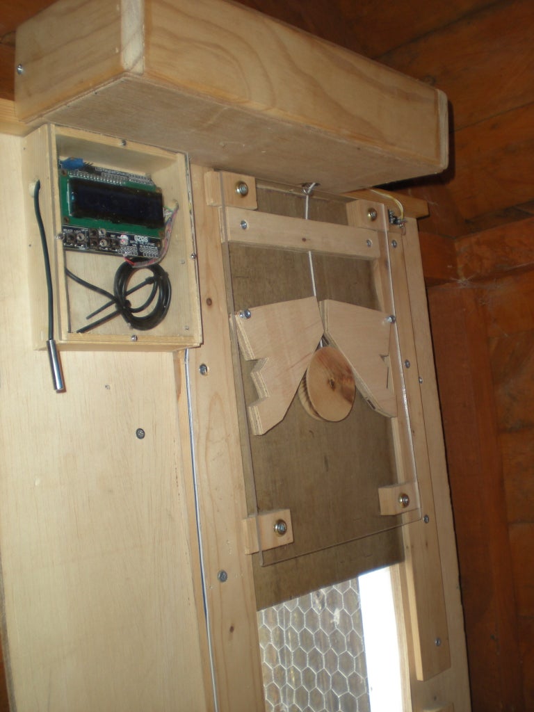
I mounted my motor on some formed wooden support pieces and left plenty of space for the motor controller and regulators. I housed the motor assembly so no moving parts would be pecked by my feathered friends - my coop isn't a tall shed. The pulley is an old wooden cotton real but any real would suffice - make sure you can drill a hole through it for the chord. As the real would only be moving for a few seconds up and down I didn't go overboard on bearings and tried to keep things simple.
I attached the real to the motor via a screw bit and some very strong double bubble glue- it goes rock hard when cured.
STEP 3: Testing the Door
I am sure there are better ways to mount everything but I must say the assembly has been working now for over 3 months and seems to be holding up well.
STEP 4: Power - Arduino, Motor and Battery
In testing I found that the motor was producing far too much noise and was severely affecting the arduino through its regulated supply. Fortunately the PCB is designed in such a way that I could separate the regulator section and feed it directly with a 9V plug power supply which immediately resolved my noise issues. I have also read elsewhere folks not recommending using the same battery for the motor and arduino.
Again this H-Bridge could be scratch built or bought as an arduino shield but do make sure the power output cables are robust enough to take the high current. I wanted to keep the heavy current unregulated circuits away from the arduino so this is why I went for this option. It is all nicely tucked behind an airy box which hides the sealed lead acid battery.
I sourced a simple and intelligent trickle charge circuit to keep the 6V battery topped up. This I managed to mount all the components on a small square of vero board. The preset pot needs to be set to provide 7.2V on the charger output (no battery attached) and will charge the battery up to 0.5A which is usually the maximum charge manufacturers recommend for 6V batteries. The motor can withstand short burst of 6-7V and in fact really helps when pulling up the door assembly.
All regulators and power amps I placed heat sinks on as the:
- H-Bridge does get warm when lifting up the door as it takes a whooping 2.5A for 3-4 seconds. I could use both channels together to provide 4A capacity but the current is only for short bursts and within the manufactures specs
- 5V regulator on the RKL298 board does get warm when the arduino display LCD light is on for viewing ACCC status
- LM137T can get warm if for any reason the 6V battery has been drained - max output is 0.5A
STEP 5: Building the Arduino Electronics
You can short circuit the work involved by choosing some excellent Arduino prototyping boards which provides RTC and connectors for probes. Do check out eBay or other distributors. The basic digital electronics needs to provide:
- Ardunio processor board based on either Atmega328P or Atmega168 (£7-£10)
- Real Time Clock based on the DS1302 or equivalent (£4)
- Onewire digital thermal DS18B20 temp probe (£4)
- Keypad Shield 4Bit 1602 LCD Module Display with an ISP header for programming using the Arduino IDE ver1.0 (£5)
- A couple of pull-up resistors and micro switches for door sensors, IDC connectors and ribbon cable (£2)
STEP 6: Testing the Logic
The code has some natural latency so by the time it stops the motor the door will be well and truly fully up or down! Once you are happy the micros switches working fine and in place do put an additional screw through the perspex holder to stop any future movement.
I found that producing a simple wooden cover for the bottom microswitch stopped the occasional failure when the door closed. I suspect my feathered friends took a liking to the wires and connectors and also thought it was a good target for their daily movements!!
STEP 7: The Code Is the Glue
I used the latest Arduino IDE 1.0 which I must say has been brilliant especially as you can now programme using the ISP programmer and not have to worry about USB dongles or circuitry. One thing I would say you still need to burn the boot loader onto your blank ATmega328 chip otherwise debugging becomes a bit of a challenge as the Arduino environment hasn't been set up properly!!!
The code I have compiled is 8,346 bytes in size so you can use the ATmega168 chip if you have a few kicking around.
Libraries:
Arduino.h - the standard and very large library
DS1302.h - Real time clock library
LCD4Bit_mod.h - Library supplied to support the LCD/Keyboard - very similar to the Standard library
OneWire.h - Provides communication to the temperature probe
Pinout Allocation and Global Variables:
This is where you need to set your own sunset and sunrise depending on your location. We have summer savings here in the UK but I decided to keep my system on GMT which means when I look at the clock in the summer saving time period it is an hour behind so the sunset and sunrise times need to be set accordingly.
Setup()
- Sets the pinouts for the motor
- Sets the display back light which is switched off on reset.
- The current MotorState is set to STOP
- The top line of the display is initialised with the status headings.
- At this point we check the temperature to initialise the min/min max settings and display it.
In the code you will notice a commented out routine 'set_time()' to set the RTC. This should be uncommented for the first time programming so the clock can be set. Comment it out and reprogramme the ATmega328 again this way if the board is reset or further changes to the code are made the RTC always has the correct time.
You need to experiment on setting the RTC in sync with the laptop time. I discovered on a Mac environment you need to allow 40 seconds for compiling and uploading to make sure the times where exactly synced.
Loop()
- Print the current time
- Pause for 0.5 second so the display can be read.
- Print the bedtime which is in total minutes with the '^' symbol in front of it.
- Print the minimum temperature with the 'v' symbol in front of it.
- Pause for 0.5 second so the display can be read.
- Print the wake time which is in total minutes with the 'v' symbol in front of it.
- Print the maximum temperature with the '^' symbol in front of it.
- Pause for 0.5 second so the display can be read.
- Print the current time
- Check the door activation button (display on/off, close door or open door manually)
- Change the Motor State according to activation button
- Check to see if it is wake time if so set Motor State to DoorUp
- Check to see if it is bed time if so set Motor State to DoorDown
- While the State Motor isn't 'Stop' call door_change to either close the door or open it and display status on screen
As you can see from the code I have created a state motor variable which ensures actions are completed before the main loop code goes back on itself.
STEP 8: Installing Into the Coop
Make sure the battery is nicely tucked away from the reach of the hens and the 9V input cable is securely attached to the door which is behind the motor housing.
I would reset the door and check the time is correct and the right sunset and sunrise minutes are displayed for that month. At the time of taking the photo's we were in March which meant the time section would display:
Actual Time Sunset Sunrise
Coop ^Coop vCoop
15:30 1140 345
Note - 1140/60 = 19:00 and 345/60 = 05:45
I left the sunrise and sunset times in mins from 12.00pm as it made a clear display distinction and was easier to translate to an opening and closing time. I was being a little lazy!!
STEP 9: What Would I Improve?
Reflecting over the build there are some improvements I will do over the next few months and no doubt publish ACCC v2.0:
- Look at putting the arduino to sleep thus conserving power. I tried running it on a rechargeable battery but the code was eating power at a rate of 40mA which meant it drained rechargeables overnight. I believe I can get it down to 10mAh or less when asleep and then normal rate for the duration of opening and closing the door
- If power can be conserved I will put a small solar panel up on the roof to trickle charge the motor and arduino batteries so it can be completely off the grid
- I would like to add an LDR (Light Detection Resistor) to one of the spare analogue lines and combine the reading to fine tune the opening and closing times. I wouldn't trigger the door opening or closing on light detection alone as it could be volatile to poor weather or the garden flood light as the fox enters our garden!
- Alternatively instead of one fixed opening and closing time each month create an algorithm that takes current and next month and works out the daily increments to the times for opening and closing
- Integrate the microswitches into the pine side rails for extra protect from nosey hens
- Create a pair of flashing LEDs to show when the door is down. At the moment we are still checking by going out to the garden. It also acts as a deterrent to vermin as they don't like anything with flashing eyes
90 Comments
ElectroLund 21 days ago
Bravo!!
mouthpear 1 year ago
Kent_In_KC 10 years ago
It amazes me what people can do. I too am a small time chicken rancher and have also wanted a way to open and close the coop automatically. ALso, there is a need to automate watering. Unfortunately, I know nothing about Arduino.
My rough concept is to use water trickling into an empty bucket on a lever (with the door on the other end of the lever) as a weight to eventually, gradually, open the door, which would ultimately tip the bucket into a water trough for the chickens to drink and close the door. Then the bucket would spring back up, right itself and begin filling again. Each fill/dump-open-close cycle would need to take about 12 hours.
I have not prototyped it yet. I do prefer simple machines that don't require a computer to operate. But, that's just me.
mouthpear 1 year ago
12 hours?! WOW. What is the source of the water movement? Pump? Heat? I came up with a way to do it with a water pump, SPDT timer, Limits switch and a solenoid valve. PVC pipe or 5 gallon buckets.
mouthpear 1 year ago
Robot-Chicken 10 years ago
itsmescotty 8 years ago
NO criticism.
But why do you need to to close the door anyway. Ive been keeping 20 hens and 1 rooster for 9 months in an 8' X 8' X 8' enclosure with a man door on one side and and a 16" X 16" opening for chicken access on the other. Oh yeah, there is an 8' X 8' skylight for a roof. The chickens are free to come and go as they please and roam around.
I had a fenced in area but the goats destroyed the fence climbing in so they are no longer fenced. When it gets dark they go in and roost and when the sun comes up they go out and 'play'. Only problem with the skylight is the full moon - rooster crows at 3am., sigh.
chickenautomation 8 years ago
I'm curious where you live that you've managed to keep chickens alive for 9 months with an open coop and run. I don't live near a nature reserve or in the wilderness. I'm in the suburbs of a large metropolitan area. We have coyote, fox, bobcat, raccoons, opossum, mink and weasels - not to mention hawks and owls. On almost every occasion I haven't made it home by dusk, I lose birds - sometimes whole flocks. Until I closed off every opening larger than 1/2", mink started attacking. In 5 nights I lost 5 flocks to mink. No meat eaten, just killed.
When it comes to raccoons, in retrospect I would have saved money by buying a premade auto coop door for every building. And saved a lot of rare birds in the process.
As for Robot-Chicken, I really appreciate the detailed sketches of the latching mechanism.
mouthpear 1 year ago
itsmescotty 8 years ago
I live on an island in the Pacific Northwest in a rural but becoming a suburbanized area with people buying 5-10 acre parcels around me and putting up fences to keep their animals in and deer out, sigh.
I acquired 20 chickens and a rooster late Oct., early Nov. Lost three then acquired another 3. Now I'm down to 14/1. I'm assuming the losses were due to Eagles as there is no shortage of them around here.
They would exit the roost at dawn and be back in bed by 7pm.
The deer and coons roamed all over the place 20 years ago but I haven't seen either for years, again sigh. There was a neighborhood dog that took out 4 of the ducks I was trying to raise and he hauled them off and I never found the bodies. With the chickens I've lost there was always a pile of feathers and if I found it early there was an eviscerated body otherwise just wings, head and feet.
On occasion I hear a coyote and have seen two. We have hawks, HUGE 'horned owls' and Eagles. It's total woods where I live but there is a clear cut area next door.
I'm experimenting with hatching, as of this morning I have three out of 17 eggs where the little buggers are escaping from their shells. Should be more later on in the day and over the next week as the incubator was added to over the course of a week. Started with 18 but one didn't candle after 10 days so I culled it. Brown, white and 'green' eggs - that's all I know about the chickens.
Turned an old fridge into a brooder for them to run around in until they are big enough to turn out into the 'wild'.
Scotty
Robot-Chicken 8 years ago
Our coup is next to a nature reserve full of foxes which have in the past devastated the coop and my little ladies!! We have also put a fence around as a first line of protection.
The other reason which you eluded to is we can keep our little darlings in the dark and release them at a more sociable time for them to cluck and forage. Having hens clucking at 4 in the morning wouldn't make me popular with my neighbours who live less than 25 yards from us in either direction.
supernoodle2014 8 years ago
itsmescotty 8 years ago
I'll see you but won't raise. Been having phone and internet problems so phone guy was here last Friday morning and we were outside fiddling with the junction box. Bald eagle with at least a six foot wing span came down 20' away in front of my cab over motor home trying to get one of the chickens that had run underneath. Hank ran around one side and I, the other. Eagle left 'empty handed' this time.
itsmescotty 8 years ago
JoustyS 7 years ago
While I'm late to the picnic... maybe my comment will help someone. I have build Arduino coop controller (motor, interior and exterior lights) and have upgraded it about 5 times.
Use old reed relay (dirt cheap or salvage) and old harddrive magnet for your limit switches, allows way easier install and less risk of breaking components of sensitive micro-switch. In my last revision I use 10" linear actuator (model DMTRL14-10, $40 on ebay). Has internal limit switches but I still use reed relay (only the switch part) and magnet to confirm door is actually closed. Use 2 LDR modules from China (Interior light comes on about an hours before door close). These modules are Photoresistor Light Detection Sensor Module for 79c on ebay. Use mosfets to control 1W LEDs for lights. Any will do with 5V despite gate rating of 10V standard. My controller also uses 4 relay board (reverse polarity of DC actuator to reverse movement). But do use the NC contacts for commons for another direction to prevent meltdown if a glitch turns on all relays at once (had it happen to me when arduino got loose on its header). Thisi s the 4 Channel Relay Board Module with optoisolation ($3 with free shipping).
I have 10W solar panel ($28) charging 7AH UPS backup battery ($26) over ebay solar controller board (DC-DC Converter 6-36V to 1.25-32V MPPT, $10).
Below is the sketch I wrote: Copy from next line to bottom:
/*
Chicken Coop Door and Light control. A 4 relay board was used (reversing polarity
to actuator motor) to close the door. Wire relay NC for one direction as COMMONs for
another in case of a software glitch to avoid all relays at the same time and a short.
There is ~5s off/delay time in door operation to prevent false ON/OFF on state changes
while in motion. Adjust variables for delays for each direction and motor time.
INT Light ON about an hour (set sensitivity) before and hour pass door close (7200s).
EXT light on pass dark until dawn (nightlight mode).
Second sensor module controls internal light as well as provides solution to 'threshold
trigger' issue where the light sensor oscillates back and fourth right at the threshold of
light trigger preset.
*/
int RelayOOut = 2; // D2 pin for relays OPEN
int RelayCOut = 3; // D3 pin for relays CLOSE
int INTLightOut = 9; // D4 pin for int light
int EXTLightOut = 4; // D5 pin for ext light
// 6,7,8 free for feed, water relays
int LSTWInput = 11; /* D11 pin for light sensor for Twilight (set to trigger before the Dusk
sensor) and INT coop light (to come on about 1h before door close).
Also provide 'treshold trigger' solution for Dusk sensor. */
int LSDUInput = 12; // D12 pin for light sensor for Dusk and EXT light (nightlight)
int intCloseDelay =30; // 60s delay to close the door past light sense trigger, must behigher than 5
int intOpenDelay =30; // 60s delay to open the door past light sense trigger, must behigher than 5
int intMotorTime = 70; // 60s for motor to completely close or open door
int intINTLightDelay=3600; // 1 hour for internal light count from LSL trigger for dark
int intTemp=0; // temp integer for operations
// dont alter variables below
int intINTLTimer = 0; // store timer elapsed (10800/5)
int isNapTime = 0; // store the LSDU read value
int isSunsetTime = 0; // store the LSTW read value
int intCDelayCount= 0; // store count
int intODelayCount= 0; // store count
bool isClosed=false; // store state: prevent inside light if lighning, etc outside
// runs once when you press reset or power the board
void setup() {
pinMode(LED_BUILTIN, OUTPUT);
pinMode(RelayOOut, OUTPUT);
pinMode(RelayCOut, OUTPUT);
pinMode(INTLightOut, OUTPUT);
pinMode(EXTLightOut, OUTPUT);
pinMode(LSTWInput, INPUT);
pinMode(LSDUInput, INPUT);
digitalWrite(RelayOOut, HIGH); //relays OFF
digitalWrite(RelayCOut, HIGH); //relays OFF
// Serial.begin(9600);
}
// runs over and over again forever
void loop() {
digitalWrite(LED_BUILTIN, HIGH); // flash board LED in a pattern to indicate 'run'
delay(10);
digitalWrite(LED_BUILTIN, LOW);
delay(100);
digitalWrite(LED_BUILTIN, HIGH);
delay(10);
digitalWrite(LED_BUILTIN, LOW);
delay(880); // total delay = 1000ms at this point
isNapTime = digitalRead(LSDUInput); // read the LS Dusk sensor input pin [high=day]
isSunsetTime = digitalRead(LSTWInput); // read the LightSensorTwilight sensor input pin [high=day]
//=========================== DOOR Relays ========================
if (isNapTime == HIGH){ // night (green LED off on the module)
intODelayCount=0; // reset variable for other direction
intCDelayCount++;
intTemp= intCloseDelay + intMotorTime; //when to run the motor
if (intCDelayCount> 5) { // if servo already running in another direction, stop it first
digitalWrite(RelayOOut, HIGH); // HIGH turns OFF O relays if ON
}
// if TW snsor dark start relay after C delay, stop at C delay + motor run time
if (((intCDelayCount > intCloseDelay) && (intCDelayCount< intTemp)) && isSunsetTime ==HIGH) {
digitalWrite(RelayCOut, LOW); // LOW turns ON C relays, closes the door [night]
isClosed=true;
}
else{
digitalWrite(RelayCOut, HIGH); // turn OFF after elapsed time
}
}
else { // day
intCDelayCount=0;
intODelayCount++;
intTemp= intOpenDelay + intMotorTime;
if (intODelayCount> 5){
digitalWrite(RelayCOut, HIGH);
}
if (((intODelayCount > intOpenDelay) && (intODelayCount < intTemp)) && isSunsetTime == LOW) {
digitalWrite(RelayOOut, LOW);
isClosed=false;
}
else{
digitalWrite(RelayOOut, HIGH); // turn OFF after elapsed time
}
}
// trim if too high counter values to prevent overflow (reset to 1 above max time)
intTemp= intOpenDelay + intMotorTime;
if (intODelayCount > intTemp) {
intODelayCount= intTemp;
}
intTemp= intCloseDelay + intMotorTime; // as above
if (intCDelayCount > intTemp) {
intCDelayCount= intTemp;
}
//=========================== Interior Lights ========================
if (isSunsetTime == LOW) { // day
digitalWrite(INTLightOut, LOW); // turns OFF LEDs
intINTLTimer = 0;
}
else {
if (intINTLTimer < intINTLightDelay) { // (DIV 1 hour timer =3600 s)
if (isClosed == false) { // door still open (check to prevent lightning triggering it at night)
digitalWrite(INTLightOut, HIGH); // turns ON LEDs
intINTLTimer++;
}
}
else {
digitalWrite(INTLightOut, LOW);
intINTLTimer = intINTLightDelay; //keep integer from increasing past too high values
}
}
//=========================== Exterior Lights (nightlight) ========================
if (isNapTime == LOW) { // day
digitalWrite(EXTLightOut, LOW); // turns OFF LEDs
}
else {
digitalWrite(EXTLightOut, HIGH);
}
//Serial.write(intDoorDelay/4);
}
//end
cberkay 3 years ago
I just love this idea! Great execution.
Do you have schematics? Do you want to share?
Best Regards
Plasterboard1 5 years ago
automaticdoors 7 years ago
Good one...
Chrome98 9 years ago
The biggest suggestion I can make to you is to use an electric linear actuator to open and close the door. This precludes the need for any locking mechanism. This is the 16" actuator I use: http://pages.ebay.com/link/?nav=item.view&id=361075336287&alt=web
fabelizer 9 years ago
Following up...3 years later...We started with 12 peeps, sold 4, 4 gone to predation (the risk of letting them run free). Arduino based Uno R3 running continuously all 3 years!
Now returned to door design for the next batch next spring. I modified some code from Roger Reed. My controller takes care of lighting, power ventilation in summer, shared with water heater for winter. (inverted flower pot with light inside). RTC will remain as a system clock. It also has a separate egg box light that flashes should the egg box be left open. One indoor temp sensor (no display :( (yet!)), but still actively in control!
Hope to add 2 more temp sensors and an indoor remote controller over rf this year...parts here, time not. The implementation of all features desired will require a mega 2560, and I am considering off loading door control to a subsystem for modularity. Light is currently relay controlled AC CFL, and will be replaced with LED pwm, filtered to remove flicker, and fading up/down to improv asthetics for the girls. Door will have a servo lock as I did not like the mechanical solution for the added weight. Locking will be verified by status LED, as will door position.
An addition I really like (for anyone considering a smlilar project) is an LED flashing a heartbeat. It is visible from the house, dims at night based on a light sensor, and provides reassurance that all is well, without being over bearing at night. It provided great feedback during the -20F temps last winter to know the system was surving and operating normally! (I was delighted the UNO clone kept on chugging through the 2+ weeks of sub 0 temps!)
Many thanks for your continued inspiration! Where is V2.0?
Cheers,
-fab