

Introduction: Arduino Desk Clock
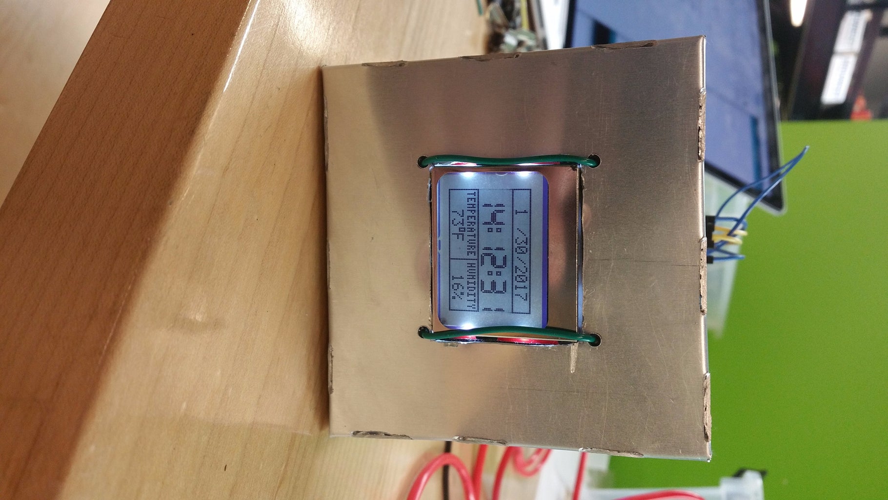
Welcome to my Arduino Desk Clock tutorial!
This project was heavily inspired by the Arduino Watch Sport by Alexis Ospitia. Here's the link to his project:
https://www.instructables.com/id/Arduino-Watch-Spo...
This clock can be powered by the internal battery, or by usb through the FTDI breakout board located in the casing.
Step 1: Gather the Materials


You will need a few things for this project:
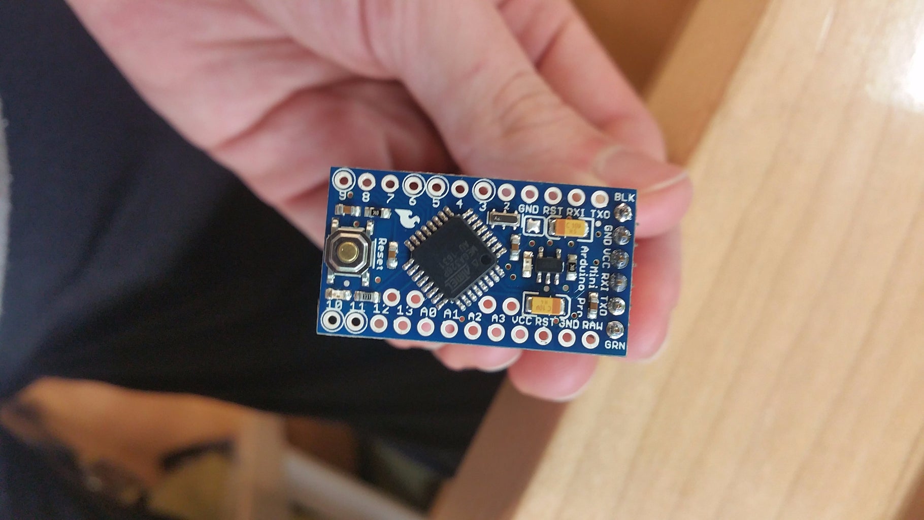
- Arduino Pro Mini 5v - 16MHz
- Nokia 5110 LCD
- DHT 11 Sensor
- FTDI Breakout Board
- 3.7v 400 MAh li Battery
- Real Time Clock - PCF8523
- 330 Ohm Resistors
- Switch for the battery
- Piece of perfboard to act as a sort of breadboard
- Aluminum Sheet
- Electrical Tape
- Wires
Step 2: Soldering Header Pins Into Arduino

You will need these pins to push code to the Arduino, since the pro mini doesn't have a direct USB connection.
Step 3: Installing the Proper Libraries
For this project, I used to following libraries:
- DHT Sensor Library by Adafruit: https://github.com/adafruit/DHT-sensor-library
- LCD_5110_Graph: https://github.com/MisaZhu/Arduino/tree/master/li...
- RTClib: https://github.com/adafruit/RTClib
The rest of the libraries needed for this project are already built into the Arduino IDE.
Step 4: Pushing Code to the Arduino

First we must connect the FTDI breakout board to the Arduino. I did this with female to female jumper cables, but different breakout boards have different headers so use whatever works.
- FTDI 3.3v goes to Arduino Vcc.
- FTDI ground goes to Arduino BLK.
- FTDI TXO goes to Arduino RXI.
- FTDI RXD goes to Arduino TXD.
- Finally, FTDI DTR goes to Arduino GRN.
After you make these connections, connect the FTDI breakout board to a USB port. Make sure to change the board in the Arduino IDE. Also, if it doesn't recognize the breakout board, you might need to install FTDI drivers.
I've attached the code for this project below.
Attachments

Step 5: Connecting the Battery to the Perfboard

- Solder switch into positive wire to be able to turn the battery on and off.
- Solder negative wire from battery into a channel on your perfboard.
- Solder positive wire from battery into the other channel on your perfboard.
We need two separate channels in the perfboard in order to power and ground all the other components of this project.
Step 6: Wiring Up the LCD


This is where you connect ground and power to the LCD. There are 2 parts of the LCD that need to be powered. One is the Vcc, which is voltage in. The other is LED, which needs a resistor in order to not blow out the LED backlights. To do this I soldered a resistor into the wire. The LED part is technically optional, but I suggest using them because I think it looks better. Finally, I soldered a wire to Ground. I also soldered wires into the rest of the spots on the LCD.
Step 7: Soldering the DHT11 Sensor
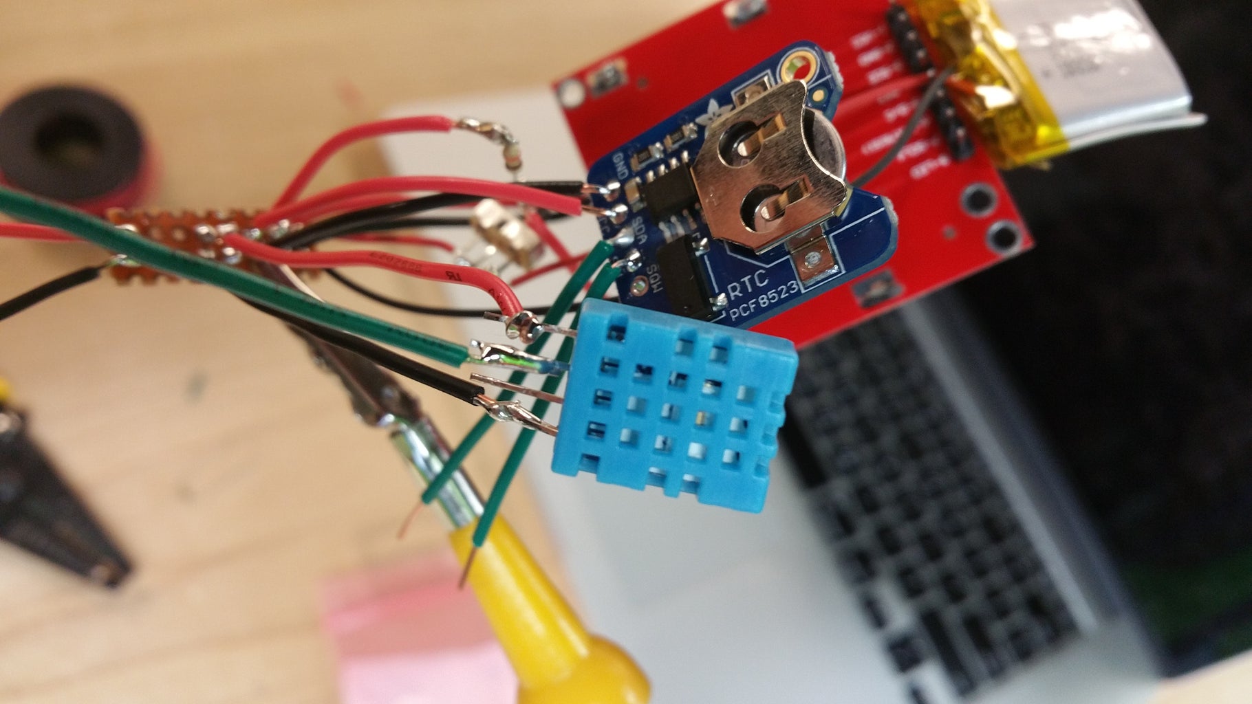
I used red wire for power, and black for ground. All other pins were green. This was the same for all components.
- Solder red wire to 1st pin of DHT sensor. This is the power for the sensor. Solder the other end of the red wire into the positive perfboard channel.
- Solder green wire to 2nd pin of DHT sensor. This is the data pin. I soldered the other end into D6. You could solder it into another digital pin, but you would need to change 1 line in the code.
- The 3rd pin of the sensor doesn't do anything.
- The 4th pin is ground, so solder a black wire to it and solder the other end into the ground perfboard channel.
Step 8: Soldering the RTC Module
Same wires as the other components: red for power, green for data, and black for ground.
- The first pin is ground, so solder in a black wire, and solder the other end into the ground channel of the perfboard.
- The second pin is power, so solder in a red wire, and solder the other end into the positive channel of the perfboard.
These next two pins must be connected like in this tutorial, or else the project won't work. A4 and A5 of the Arduino are special I2C pins.
3. Solder in a green wire into the SDA pin of the RTC. Solder the other end into A4 of the Arduino.
4. Solder a green wire into the SCL pin of the RTC. Solder the other end into A5 of the Arduino.
Step 9: Soldering LCD Wires Into Arduino


The LCD has the most wires to solder in. Let's go in order as seen on the diagram above. You should have wires soldered into the LCD from an earlier step.
- 1st is VCC, which is power. Solder red wire into the positive perfboard channel.
- 2nd is GND, which is ground. Solder black wire into the ground perfboard channel.
- Next is SCE. Solder green wire from SCE to D12.
- 4th is RST. Solder green wire from RST to D11.
- 5th is D/C. Solder green wire from D/C to D10.
- 6th is DN. Solder green wire from DN to D9.
- 7th is SCLK. Solder green wire from SCLK to D8.
- Finally, is LED. This is the one with the resistor integrated into the wire. Solder this red wire into the positive channel of the perfboard.
Step 10: Soldering Power and Ground Into the Arduino

- Solder a red wire from the positive channel of your perfboard into VCC on the Arduino.
- Solder a black wire from the ground channel of your perfboard into GND on the Arduino.
Step 11: Solder Power and Ground Into Perfboard

I soldered power and ground for each component into the perfboard. I then soldered the channels together so that each component would be getting power and be grounded. Make sure you don't solder the 2 separate channels together or else you will have problems.
Step 12: Creating the Enlcosure


- I started by creating a 3.25 inch cube net on the front of it, but with one side missing.
- Use a Dremel to cut the net out and score the net alone the lines.
- I folded the net in along the lines to create a box with an open top.
- Measure out a piece of the cube to fit the screen into it. Cut the piece out.
- Next I created the back piece that would close off the box.
- Fold over tabs in the main cube to be able to drill holes into them later.
- Drill the holes into the back piece and the tabs to connect them together later.
- Cut hole for the DHT Sensor, as well as holes for the Arduino pins that could be used to power the clock through USB.
Step 13: Putting It All Together

- Insulate the inside of the box with electrical tape. This will prevent any electrical problems.
- Stick all the electronics into the box. Have the LCD face out.
- Use the holes you cut for the LCD screws to secure the LCD to the front of the box. My holes were too small for my screws so I used some wire like people use when shopping for groceries when they put their vegetables in a bag.
- I used some velcro to stick the Arduino in the spot I needed.
- I did the same thing for the back of the enclosure like I did for the LCD.
- Finally, I connected the wires to have it powered on and on my desk.
