Introduction: Arduino Knock-Knock Treasure Box


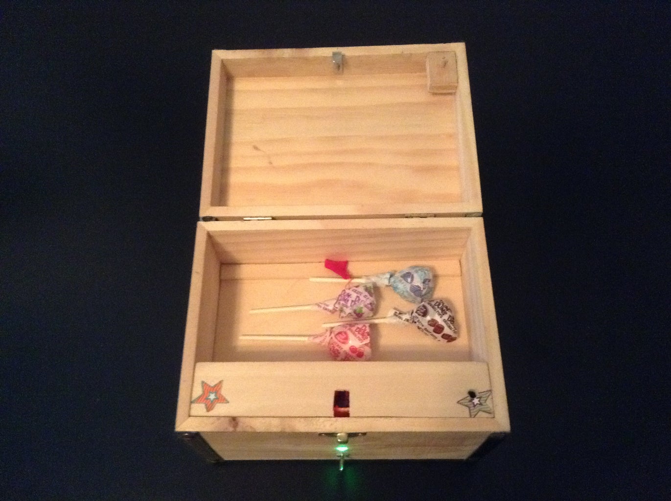
This is my first Arduino project and Instructable. I made it for my three young grandchildren who have enjoyed it greatly. I purchased the box from Jo-Ann Fabric and Craft Store and installed an Arduino system. I put treats in the box and program a secret knock by knocking on the box. When they visit they immediately rush to the Treasure Box and work at finding the correct knock. When successful, the box lid springs open and they retrieve their treats.
Step 1: Design Overview


Refer to the photos.
The box has a power switch and a red/green/blue (RGB) LED on the front.
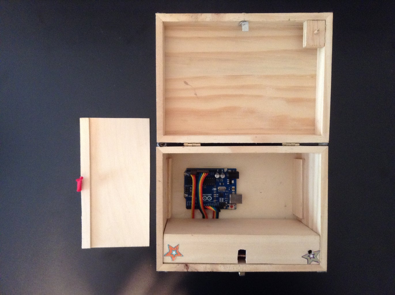
Internally, an Arduino Uno on box bottom and a circuit board on box front are hidden and protected by two covers: a false bottom and a front (circuit board) cover.
The modules interconnect with three ribbon cables.
The front cover slips over the circuit board. The false bottom presses into the box and against the front cover to hold it in place; i.e. no screws are required for the cover and false bottom. A piece of fabric glued to the false bottom enables easy removal.
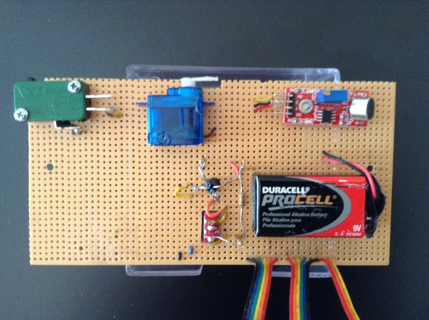
The circuit board has a 9V battery, microphone knock sensor, servo for locking, lid micro switch, resistor voltage divider for battery monitoring, and also carries the power switch and LED.
The voltage divider has two identical resistors in series. Battery 9V is attached to one end and ground to the other. Nominal center tap voltage is 4.5V and that is fed to one of Uno's analog ports, which are scaled to 5V.
The box works as follows.
PROGRAM MODE
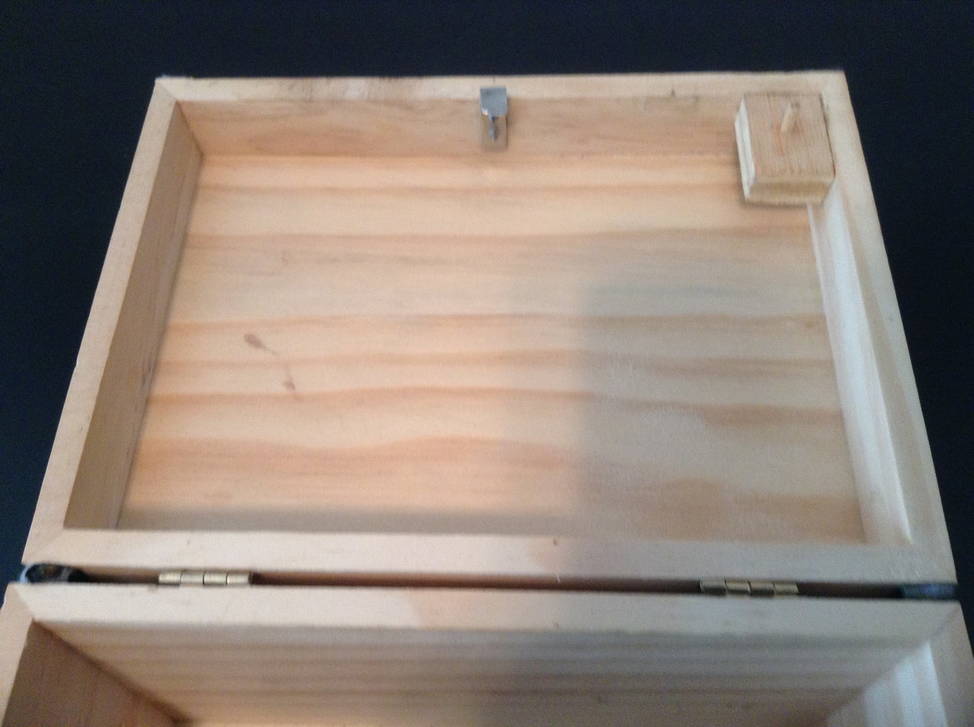
The box will normally be left with lid ajar, held open by the spring action of the lid micro switch.
Flip the power switch on. The LED glows green. And , if not already unlocked, the servo will go to unlock position. This is Program mode, determined by the micro switch in open state.
The box will not lock in this mode and will not respond to knocking or lid closures less than 5 seconds (or other value specified), until the lid is held down for more than 5 seconds.
Press the lid to close it and keep it closed until the LED blinks after 5 seconds.
Then release the lid and Program mode is ready to receive your secret knock. If the lid is released too soon the box will show no LED indication but will accept another closure.
(The 5 second lid closure requirement for entry to Program mode is a safeguard against possible lockout. The 5 second requirement helps to avoid unwanted Program mode entry due to accidental lid bumps or kid fiddling, and therefore guards against accidental programming and your inability to perform an unknown secret code to open a locked box. The lack of LED flashing to show error for early release is deliberate to reduce kid's interest in fiddling.)
Open the lid and perform a secret knock by knocking on the front cover.
The LED blinks for each knock detected.
There is a pause while knock data is stored in Uno EEPROM.
Then the LED blinks to verify data store.
Before locking the box it is a good idea to test the knock.
To do this I use one of the kid's lollipop sticks to briefly depress the lid micro switch (simulated lid closure) while flipping the power switch off then on, causing the servo to go to lock position and the LED to go red. (This is Operate mode.) I then enter my knock on the front cover. If the knock is correct the servo will go to unlock and the LED will go green.
Flip the power switch off. Then hold the lid own while switching power back on.
The box locks and the LED glows red. The box is now in Operate mode and ready for the kids.
(Assuming that treats have been placed in it!)
Flip the power switch off.
OPERATE MODE
The kid flips the power switch on and the LED glows red.
He tries a knock. The LED blinks for each knock detected.
If the knock does not match the secret knock (within a defined tolerance) the LED flashes rapidly for a few seconds and the box will then accept another knock
If the knock does match, the LED goes green, the servo unlocks, the lid springs open, and the kids retrieve their treat.
The box will not respond to further knocks or lid closures until the power switch is cycled.
The kids can set up the box so that one of the others can take a try at the same secret knock.This is done simply by holding the lid closed while flipping the power switch on.
If you get locked out of the box I have provided a way to unlock it: just knock 10 times within the 5 second allowed time and the box will open. It is unlikely that a kid will do this.
BATTERY MONITORING
When the power switch is flipped on, Uno reads battery voltage (divided by two).
If that corresponds to less than the 7 volts specified for Uno, the LED goes blue and blinks rapidly.
If that happens the box will not go to Program or Operate mode until the battery is replaced.
THE CIRCUIT BOARD
The circuit board is a perfboard holding all of the electrical components listed above. Wiring is point-to-point on board back.
Except for the power switch and LED, all circuit board components mount to the board with double-sided foam tape. This is especially convenient for servo and micro switch positioning.
The power switch and LED float so that they can be pushed through their holes in box front.
The circuit board is a standalone module that can be operated out of the box when connected to Uno.
The lid micro switch depressor is a wood dowel mounted in a small block of wood in the lid. The dowel passes through the hole in the front cover to engage the switch.
The lid latch is an aluminum L-bend. It passes through a slot in the front cover to engage the servo, whose arm swings over it
to lock the lid.
The latch screws to the lid with screws inserted from the outside. This enables easy latch removal to gain entry to the box in case of lockout due to forgotten secret knock, dead battery, or electrical failure.
Step 2: Parts, Material, and Tools
PARTS
Box - Available at Jo-Ann. $6 with coupon.
Uno - You probably have the Uno. If not, it is available at Radio Shack or online at Sparkfun, Jameco, etc, for $28-$35.
Microphone board – Online at DealExtreme 135533 (only $2.80 with free shipping).
Servo – I had a Hitec HS-55. You can buy one for $10 or gamble on Chinese quality for less.
Micro switch – Sparkfun COM-09506 $1.50
RGB LED - Radio Shack has one for $1.
Power switch – Jameco 76523 $1.49 (This was the only one I could find that had sufficient thread length to pass through the 1/4 inch box front and use the nut.)
9V battery – Also get a snap connector.
Ribbon cables(3) – Sparkfun 12 inch:
5-pin PRT-10375 $1.95
4-pin PRT-10374 $1.95
2-pin PRT-10372 $1.95
Resistors:
One 1,000 ohm (current limiter for my bright LED)
Two 10,000 ohm (for the voltage divider)
All can be 1/8W.
MATERIAL
Perf Board - Radio Shack 6 x 8 inch board 276-1396 $3.49
Tape – Scotch Permanent Mounting Tape (double-sided foam tape).
Stranded Hookup Wire
Heat Shrink Tubing – 1/4 inch and 1/16 inch diameter.
Nylon standoffs (3) – 1/4 inch high to mount Uno. I got mine at Ace Hardware.
Wood – 1/8 inch thick x 24 inch long bassboard from Jo-Ann. One 3 inch width and one 4 inch width.
Wood Dowel – One each I/8 inch diameter and 1/4 inch square.
Glue – I like Aleene's Tacky Glue. Holds parts in place while drying, dries in a few hours, sticks to about anything, and holds well.
Aluminum – I had a .032 inch aluminum sheet that I got at Home Depot. I cut the latch from that. You could use the aluminum top from a $3 Radio Shack project box, part # 270-1801.
Screws:
Two #4 x 1/2 inch sheet metal screws to attach the latch.
Two #4 x 3/8 inch screws to hold the circuit board in place.
Three #4-40 x 1/2 inch machine screws and nuts to mount Uno.
TOOLS
Wire cutter
Wire stripper
Soldering iron and solder
Fine-toothed Saw for the wood - If you don't have a table saw, you may be able to use a hacksaw
Coping saw (for notching)
Hacksaw for aluminum
Drill and bits
Vise – Nice to have for for holding material while cutting.
Step 3: Make the Circuit Board
Cut out the perfboard. The 6 inch dimension of the Radio Shack perfboard works as-is for width, clearing the 1/8 inch sides of the cover. Cut a piece off the 8 inch dimension that equals the interior box depth, less 3/16 inch to clear the top of the cover, which is flush with the box top lip.
Mark drill points on the box outside front face, horizontally centered, for the power switch and LED.
Center the perfboard in the box and drill pilot holes through box and board.
Enlarge holes to fit the switch and LED.
Using the coping saw, enlarge the perfboard switch hole to a rectangle that passes the switch.
Also cut a 1/2 inch wide x 1/4 inch tall notch at board top center. This allows clearance for the aluminum latch and servo arm.
Cut four basswood strips equal to perfboard height. Glue these together to make two 1/4 inch thick mounts for the perfboard.. These will provide space for the wiring.
Position the mounts on perfboard left and right edges and drill a pilot hole at mount center through perfboard and basswood.
Screw the perfboard to the mounts, apply glue to the mount exposed side, and stick it to box front, keeping the perfboard centered.
Let dry, then unscrew perfboard.
This leaves nice spacers and avoids trying to make pilot holes in the cramped confines of the box interior.
Now tape the micro switch, servo, microphone board, and battery to the perfboard, referring to the photo. Also place the voltage divider resistors on board. The servo arm in lock position should be where the lid latch will be, centered left/right on the box.
I enclosed my LED in 1/4 inch diameter heat shrink and slipped 1/16 inch diameter heat shrink over two of the four leads to insulate them all from each other. The only heat shrinking I did was around the LED glass bulb to hold the LED firmly. Length of the larger heat shrink was 1.25 inch to equal box thickness and spacer thickness, plus protrusion from the perfboard. I made 90 deg bends in the four leads, preparatory to soldering.
Cut one connector off each ribbon cable.
Break headers off the 40-pin breakaway male header strip and plug them into the remaining three female connectors. They will plug into Uno's female headers.
Step 4: Wire the Circuit Board


Decide where Uno will mount, considering front cover depth (1.25 inch; see Step 5) and leaving room to plug in the USB cable.
With ribbon cables plugged into Uno, determine the length needed from mounted perfboard bottom to Uno and peel the ribbon wires apart to that point.
Enlarge the perfboard holes to permit feeding the wires through. Pass the wires through the holes, trim as necessary, strip the ends and solder to the circuit board components. Wiring data is given below.
DIGITAL SIGNAL CONNECTOR
Component Connection Uno Port
Blue LED Anode 8
Red LED Anode 9
Green LED Anode 10
Servo Angle Cmd 11
(yellow wire)
Micro Switch 12
(normally closed lug)
POWER CONNECTOR
Component Connection Uno Port
5V input 5V
Ground Gnd
NC Gnd
Switch 9V output Vin
ANALOG CONNECTOR
Component Connection Uno Port
Microphone Board A0
Voltage Divider A1
Additional wiring is:
Wire battery 9V to switch input.
Wire 5V from Uno to servo (red wire) and microphone board “+” pin.
These three wires can be twisted together, soldered, and covered with heat shrink.
Wire all component grounds to Common Ground:
Battery (black wire)
Microphone board (“G” pin)
Servo (black wire)
Micro switch lower lug
LED cathode resistor
These wires can also be twisted together, soldered, and covered with heat shrink.
Note that all wiring is done on the back of the board. Wires to components pass through enlarged holes where necessary. The LED cathode resistor is soldered to that pin and passes through a standard hole to the ground connection below.
Step 5: Make the Front Cover and False Bottom
FRONT COVER
Cut the sides, top, and back from the 3 inch wide basssboard using the following measurements:
Sides height equal to interior box depth minus 1/8 inch . This leaves the cover top flush with the box front top.
Width of 1.125 inch, which should leave sufficient room for the circuit board.
Top length equal to box interior width.
Width equal to sides plus 1/8 inch to overhang the back.
Back length equal to top.
The 3 inch board width can be used as is. It leaves a gap at the bottom for the ribbon cables.
Cut two lengths of the 1/4 inch square dowel equal to the length of the sides.
Referring to the photos, glue the sides to the back, flush with back sides and top. Glue in the square dowels for reinforcement.
Glue the top to the sides and back.
FALSE BOTTOM
Cut four false bottom supports from basswood. These glue together in pairs to provide two 1/4 inch wide supports that glue to box sides.
Length is arbitrary but height must allow the false bottom to clear the ribbon cables when plugged into Uno.
Cut the false bottom from the 4 inch basswood.
Dimensions equal box interior dimensions, minus the 1.25 inch occupied by the front cover.
If necessary to achieve a press fit to the front cover, cut a narrow length of basswood equal to box width and glue it to the rear of the false bottom while it is in the box, pressing the strip against the box back. (See the photos.) You can use wax paper to assure no gluing to the box.
Step 6: Install the Circuit Board and Uno
Screw the circuit board to the spacers using the two #4 x 1/4 inch screws.
Position Uno on box bottom so that the ribbon cables easily plug in, and leave room for the USB cable.
Mark three mounting holes (the fourth is hard to use) and drill for the machine screws.
Use the three machine screws, nuts, and nylon spacers to mount Uno.
Stick four felt pads to box bottom to provide clearance for the protruding screws and nuts.
Step 7: Make and Install the Lid Parts
LATCH
Cut a strip of aluminum 1/4 inch wide and 1.5 inches long.
Make a 90 deg bend extending about 3/8 inch.
Remove the box latch.
Install the aluminum latch with two screws in the following manner:
Hold the latch inside the lid at lid center and drill one pilot hole through lid and latch for a screw.
Enlarge lid hole for screw shaft.
Screw the latch on, lining it up vertically.
Repeat for second screw.
Adjust the servo as necessary to align the latch as close as possible with the top of the servo arm.
(The best way is to make careful measurements since vision is limited. Final adjustment can be done by bending the latch until there is just a little play in the lid when locked.)
MICRO SWITCH DEPRESSOR
Make a 3/8 inch thick block of wood to go in the corner of the lid with a 1/8 inch center hole to hold the dowel. The dowel must be centered on the micro switch plunger when lid closes; final adjustment can be done by positioning the switch. Glue the block in place.
Cut a 3/4 inch piece off the dowel.
Slide the dowel nearly all the way into the block hole; enlarge hole diameter as necessary.
Dab glue on dowel end and close the lid to mark the cover hole position.
Drill the hole.
Push the dowel partly out of the block and adjust length while listening to the switch click.
Mark where the dowel enters the wood block.
Pull it out, apply glue, then glue it back in.
Do a final micro switch adjustment if necessary to approximately align switch plunger with the cover hole.
Step 8: Download the Sketch File and Move It to Your Sketchbook
The sketch file is on Dropbox. It is named KnockKnockTreasureBox_9.ino This is a copy of the same file that is in my Sketchbook.
Use this link to download: https://www.dropbox.com/s/a0dqwk3ziauz2ir/KnockKnockTreasureBox_9.ino
Copy or move this file from your Download folder to your Sketchbook.
In the Arduino IDE click on Sketchbook. Then click on KnockKnockTreasureBox_9 to view it.
The sketch is heavily commented and designed for easy reading by anyone familiar with Arduino coding.
It uses two libraries: Servo.h and EEPROM.h
In most places a variable name is used rather than the value I used. Thus the value may easily be changed where the variables are typed and defined. For example, Uno ports are named rather than numbered in the code.
It makes strong use of Functions. This keeps the main program [loop()] simple because it calls up functions which are clearly named and in which the details of the sketch are accomplished.
The main program listing follows. It is not for compilation but is presented in nearly that form for your understanding. The Functions are bold font for easy recognition and are described following the main program listing.
MAIN PROGRAM: Void loop() {
CheckBattery() / /Flashes blue if battery needs replacing and will not proceed.
[If lid switch open go to ProgramMode]
Else goto OperateMode
ProgramMode:
[Unlock the servo and light the green LED]
AwaitGoAhead() //Waiting for user to press lid for 5 sec to enable more secure programming.
ReadyToProgram: //A goto address
GetKnock() //Wait for user knocks, determine number and time between each, test for legality,
If ErrorFlag == 1 //Set flag if illegal,
FlashLED() //Flash LED.
goto ReadyToProgram //Try again
StoreSecretKnock() //Store secret knock data in EEPROM
BlinkLED() //Blink LED to show data was stored .
ProgramDwell: //Disable box response to further lid closures and knocks.
goto ProgramDwell
OperateMode:
[Lock the box and light the red LED]
GetKnock()
If ErrorFlag == 1
FlashLED()
goto OperateMode
GetSecretKnock() //Retrieve data from EEPROM
CompareKnocks() //Compare knock number and spacings for user's knock vs secret knock.
If ErrorFlag == 1 //Set flag if different, and flash LED.
FlashLED()
goto OperateMode //Try again
[Else, light the green LED and unlock the box]
Dwell: //Disable box response to further knocks or lid closures.
goto Dwell
FUNCTIONS
CheckBattery() reads the 0-1023 reading of analog port A1 and converts it to volts.
If voltage is less than 7V it starts flashing the blue LED and freezes the program in this state until power is turned off. However, If voltage is less than 5V the box is being USB-powered, so blue flashing is disabled.
AwaitGoAhead() senses lid closure, waits for 5 seconds, blinks the LED, waits for lid to open, then returns to main program.
GetKnock() is called in both Program and Operate modes. It computes and saves the time interval between each knock. It also determines if the time allowed for knocking or the maximum number of knocks allowed has been violated, in which case it sets an ErrorFlag.
It waits until a knock amplitude on analog port A0 exceeds set Threshold.
When the first knock (N = 0) occurs it reads clock time and saves it in the Time[N] array as Time[0]. It also blinks the LED.
Clock time is constantly being read and ElapsedTime computed
as Clock – Time[0].
If elapsed time exceeds the allowed time for trying knocks, and only one pulse has been detected, the ErrorFlag is set and the function returns. Otherwise the function returns with no set ErrorFlag.
For each knock (N) detected after the first knock, ElapsedTime is saved as Time[N], and the LED is blinked.
If the number of knocks exceeds the maximum allowed (10), the ErrorFlag is set and the function returns.
If there are no errors, each knock interval (Time[N] – Time[N-1]) is saved in array KnockInterval[N], and when allowed ElapsedTime is reached the function returns.
StoreSecretKnock() is called in ProgramMode. It stores in EEPROM each KnockInterval[N] saved in GetKnock(), as well as total KnockNumber. These are stored as SecretKnockInterval[N] and SecretKnockNumber.
GetSecretKnock() is called in OperateMode. It retrieves each SecretKnockInterval[N] and SecretKnockNumber saved in EEPROM.
CompareKnocks() first determines if the KnockNnumber saved in GetKnock() equals the MaxKnockNumber allowed (10); if so, the box will open. This is a way to open a box when you are locked out.
Next, this function determines if KnockNumber from GetKnock equals the SecretKnockNumber retieved from EEPROM. If not, the ErrorFlag is set and the function returns.
If OK, the function compares each KnockInterval saved in GetKnock() to each SecretKnockInterval retrieved from EEPROM. If not equal, to within the Tolerance set in Delta, the ErrorFlag is set; otherwise the function returns with no ErrorFlag set.
BlinkLED() and FlashLED() are simple, short routines that do just what they say.
Step 9: Compile and Upload the Sketch; Then Test Your Box
Compile and upload the sketch to Uno using your USB cable.
Unplug the USB cable and flip the power switch on to operate on the box battery (a good one!).
The LED should be green.
Hold the lid down for less than 5 seconds.
When you release the lid nothing should happen; the box is waiting for more than 5 seconds hold-down to minimize the chance of unwanted secret knock entry.
Now hold the lid down until the LED blinks.
The box is now ready for you to enter a secret knock.
Open the lid
Program a secret knock by tapping on the front cover.
The LED should blink for each knock and blink again when the knock is saved.
(If you enter only one knock or too many knocks in the allotted time (5 seconds) the LED will flash.
You can then enter another secret knock.
Go ahead and test this now.)
Now, remember to test your secret knock before locking the box!
Test as follows.
Flip the power switch off.
Depress the lid micro switch with whatever is handy and flip the power switch back on.This simulates locking the box and going into Operate mode.
The servo should “lock” and the LED should now be red.
Enter the secret knock by tapping on the front cover.
The LED should blink for each knock.
After a short wait the LED should go green and the box should unlock.
Now try knocking. Nothing should happen.
Try closing the lid
Nothing you do should have any effect.
Box operation is deliberately disabled after successful unlocking to discourage kid fiddling.
However, the power switch can be cycled to start the process again.
If the lid is held down while power is turned on the box should start up in Operate mode with the previously stored secret knock.
This is useful when one kid has opened the box and another wants to try his luck.
Go ahead and do this.
You can enter repeated knocks as long as you want.
Exercise box error response by entering other than the secret knock. The LED should blink for each knock, and after a short wait the LED should flash rapidly to tell you that was not a good knock.
Enter some illegal knocks. Try: a single rap; taking more time than allowed while knocking; using more than the allowed number of raps. Each illegal knock should get the LED flash response.
Perform the secret knock and the box should spring open.
Lock the box again by flipping the power off, holding the lid down, and flipping the power back on.
Knock 10 times rapidly (within 5 seconds).
The box should open.
This is the emergency open command.
The easiest way to test battery monitoring is to clip leads from a variable voltage bench power supply to the battery connector, being careful about polarity and clip attachment. However, if you've got a used battery with a little less than 7V, that is much safer.
The box LED should flash blue when voltage drops below 7V.
Step 10: Some Concluding Notes
I made two different boxes.
Old Box
This box had Uno mounted in the bottom, jumper-wired to a small breadboard in the bottom.
The knock sensor was a piezoelectric in the lid. The LED was also in the lid.
This meant having a ribbon cable snaking down to the breadboard.
The servo was a standard (larger) servo screwed to a sturdy wood mount extending from box bottom
with Its standard 3-pin cable plugged into the breadboard.
A smaller micro switch was glued to the box front. I also used this for awhile on the new box until it failed.
(You may have wondered about the star sticker over the hole on the front cover of the new box pictured in this Instructable. It hides the ugly hole necessary for the new micro switch! The second star just balances the first.)
One ribbon cable served the micro switch and power switch. It too plugged into the breadboard.
The 9V battery was taped to box bottom and cabled to the breadboard.
Lastly, a “hidden” 3-position slide switch was screwed into the outer bottom of the box and operated by reaching under the box. It was ribbon cable connected to the breadboard.
This switch selected three modes: Program, Operate, and Open.
The last function allowed the box to be opened at any time.
This switching function worked well, but eventually the kids discovered it and could then open the box at will. Also, there was the possibility that they could put in their own secret knock, although it wasn't really a problem since I could select Open or select Program to change the secret knock.
In the new box I tried using a stereo jack and plug to achieve a “dongle” that would allow box Open.
That's why there is yet another star on the box bottom covering the required hole.
The dongle worked but was a little clumsy. I eventually decided on the security approaches described herein.
Battery monitoring was not included in the first box.
A surprise using it in the new box was the fact that it triggered the blue flashing when USB was plugged in, and box operation was disabled. Fortunately, a simple one line of code fixed the problem.
New Box
The old box had 5 ribbon cables, Uno, breadboard, and battery in box bottom. The exposed servo, micro switch, LED, and power switch were mounted on box front. This created a product that was very messy and somewhat difficult to install and work on.
That is what motivated the design of the new box:
Hide everything
Eliminate screws
Eliminate the breadboard interface
Minimize number of cables
Go to a single removable module (circuit card) for everything but Uno.
I didn't quite achieve the no-screws criteria.
My intent was to use magnets to hold the circuit board in place; four magnets glued to box front and four ferrous metal plates on circuit board back. However, locally obtainable magnets proved to be too weak. So I used two screws. If you look close you may see that I kept the glued-on magnets as spacers and didn't take the plates off the board. If I had taken the time to find and procure the right magnets, I'm sure this would be a good design. The spacer approach I described will avoid the problem of driving screws in the box front.
I had some trouble keeping the micro switch taped on, so I added two screws.
I could probably avoid screws by gluing but I took the easy no-risk way out.
I plan to replace Uno with an Arduino Pro Mini 328 board that will mount in the unused space seen in the lower left corner of the circuit board. This will serve to eliminate the false bottom, increase treat space, and further streamline the design. Perhaps then I can also magnetically mount the board and the cover and glue the micro switch. So far the foam tape is doing a fine job of holding the servo, microphone board, and battery.