Introduction: Arduino Robotic Arm

This instructable was created in fulfillment of the project requirement of the Makecourse at the University of South Florida.
These are the basic components required to assemble this project
Supplies
(3) 9g Micro Servos
(1) Arduino board w/ USB connector
(2) Breadboard (regular size and mini)
(1) Rectangular enclosure
(1) Stepper motor
(1) Pack of jumper wires
(1) Servo controlled clamp
(1) IR sensor
(1) IR remote
(1) Resistor
Step 1: Control Circuit
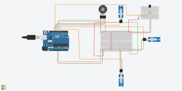
Set up the control circuit as show in the figure
Step 2: Sketch

Upload the provided sketch onto the Arduino.
After uploading sketch, the circuit should operate using the IR remote.
Step 3: Sketch Cont..

Step 4: Sketch Cont..

Step 5: Sketch Cont..

Step 6: Stepper Libraries

Go to the following link to download the StepperAK.cpp and StepperAK.h files and place them into the same folder as the previous sketch.
Link: https://makecourse.weebly.com/week8segment2.html
Step 7: 3D Design (Arm)

This part of the robotic arm is considered as the actual arm of the robot. This will have two servo motors connected on both ends. This part connect the base of the arm to the clamp.
Step 8: 3D Design (Hand)

This designed part serves as the hand of the robotic arm in which the servo controlled clamp is connected to. This part moves up and down to lower or rise the clamp to the desired position.
Step 9: 3D Design (Base)


These three parts are used as the base of the robotic arm. The circular part has a hole in its center where the stepper motor shaft is fitted into. The two flat pieces are fitted inside the slits located on the circular piece. The larger, triangular-top flat piece is where the "arm" and servo motor is to be connected.
Step 10: 3D Design (Base)

This part is also used for the base as the stepper motor will be fitted underneath of this piece so that the shaft is pointing out. The visible part of the shaft is where the circular base part mentioned previously is to be connected to.
Step 11: Printed Design

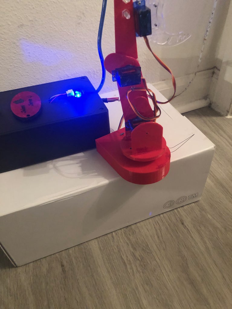
This is a visual of how the product should look.
The parts were drilled and held together using bolt and nut along with super glue.
The clamp was bought from amazon and installed to the top of the "hand" piece to enable the robotic arm to pick up things.
Step 12: Enclosure

The Arduino and breadboard are placed inside of the plastic enclosure to prevent circuit from disassembling and making the overall presentation of project easier.
Holes were drilled inside of the enclosure to run the wires through.
The mini breadboard was fastened onto the top of the enclosure due to the fact that the IR receiver was fitted to it and it needs to be exposed in order to work with the IR Remote.