Introduction: Arduino Robotic Hand

This instructable was created in fulfillment of the project requirement of the Makecourse at the University of South Florida (www.makecourse.com).
Supplies
The basic components that will be used to create the robotic hand are the hand itself, which will be 3D printed, rubber bands, fishing string, a plastic box, two micro servos, a push button, an Arduino Uno, and a small breadboard.The hand will be mounted on a plastic box which will contain all the components inside it. The Arduino reads a push button on the outer part of the box and triggers the servos to rotate 180 degrees.The servos will pull string that acts as tendons, allowing the fingers to move.
Step 1: Gather the Materials


- 2x MG946R Servos
- 1x pushbutton
- 1x Arduino Uno or equivalent
- 1x small breadboard
- 2x #4 3 inch screw
- 16x #4 1.5 inch screw
- Breadboard jumpers/hookup wire
- Hot glue
- Super glue (C.A. glue)
- Fishing string
- Black Paint
- Rubber Bands
- A power drill
- A soldering iron
- Access to a 3D printer
You're ready to begin!
Step 2: Print the Hand
Download and print all the following parts:
Attachments
 Ring_Finger_Bottom_692781_A.stl
- Ring_Finger_Middle_692781_A.stl
- Ring_Finger_Top_692781_A.stl
- Thumb_Bottom_Piece_692781_A.stl
- Index_Finger_Bottom_Part_692781_B.SLDPRT
- Index_Finger_Middle_Part_692781_A.SLDPRT
- Index_Finger_Top_Part_692781_A.SLDPRT
- Middle_Finger_Bottom_692781_A.SLDPRT
- Middle_Finger_Middle_692781_A.SLDPRT
- Middle_Finger_Top_Part_692781_A.SLDPRT
- CutBase_692781_B.SLDPRT
- Pinky_Bottom_Part_692781_A.SLDPRT
- Pinky_Middle_Part_692781_A.SLDPRT
- Pinky_Top_Part_692781_A.SLDPRT
- Thumb_Top_Part_692781_B.SLDPRT


Step 3: Making the Circuit

The main GND (ground) wire, is connected to the negative (-) end of the breadboard. The +5V from the Arduino goes to the positive (+) end of the bread and will be used to power the motors.
Each of the servos will be connected to the negative and positive side of the breadboard. So they will be grounded and will receive 5 volts of power. As seen on the diagram the black cable corresponds to ground and the red cable corresponds to power. Furthermore, each servo will be connected to a pin of the Arduino. I have used pin 2 and 3 in my code.
The push button will also be connected to ground through the negative end of the breadboard, as well as power through the positive side of the breadboard. I also connected the push button to pin 4 of the Arduino. I soldered the push button to longer jumper wires instead of keeping it connected through the breadboard.
Step 4: Assemble the Hand
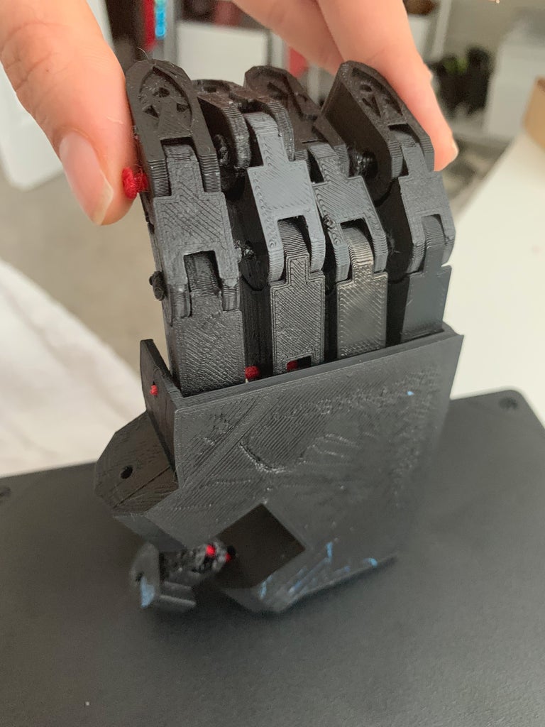
When assembling the fingers make sure the parts are placed in the correct order before screwing together. Build each individual finger first by using the #4 1.5 inch screws to attach the bottom, middle, and top piece of the finger together. Once each individual finger has been assembled, use one of the #4 3 inch screws to attach the 4 fingers to the hand. Then use the second #4 3 inch screw to attach the thumb to the other side of the hand base.
Use the drill to create one hole centered at the inner part of the top of each finger. Then place the small screws within these holes. Tie the fishing wire to each of the screws.
Once again use the drill to create holes, this time on the outer part of the hand base. Create 4 holes, each one centered with its corresponding finger. Place a screw in each hole. These will later be used to attach the rubber bands, so don't screw them all the way in.
Step 5: Placing Everything in the Box

Drill two 1.5 cm diameter holes on the longer side of the box, one 2 cm hole on the short side of the box, and one .5 cm hole on the front right corner of the top of the box.
Hot glue the two servo motors to each of the 1.5 holes. Place the Arduino and bread board with all the wires inside the box. Then, pass the push button through the small hole. The large hole will be used to power the Arduino. You can now close the box and screw the top back on.
Super glue the base of the hand and the push button to the top of the box.
Tie the loose ends of the fishing wires to the servo motors.
Step 6: Code
This is the code you will need to upload to the Arduino in order for the hand to function by pressing the push button:
#include // includes the servo library
Servo servo1; // initializes servo #1
Servo servo2;// initializes servo #2
#define buttonPin 4// defines pin 4 as the pin for the push button
byte buttonState;// stores number for the button state
int i = 0;
void setup() {
digitalWrite(buttonPin, LOW);// disables the internal pullup on the input pin (button pin)
pinMode(buttonPin, INPUT);// configures button as an input
digitalWrite(buttonPin, HIGH);// enables the internal pullup on the input pin (button pin)
servo1.attach(2);// attaches servo #1 to pin 2 of the arduino
servo2.attach(3);// attaches servo #2 to pin 3 of the arduino
}
void loop() {
buttonState = digitalRead(buttonPin);// sets the button state as the reading value of the button pin
if (buttonState == LOW) {// tells the arduino what to do if the value of the button state is low
for (i = 0; i < 180; i++) { // sets the angle of rotation of the servo to 180 degrees
servo1.write(i);//turns the servo in full speed by altering i to a value closer to 90 degrees the servo slows down servo2.write(i); //turns the servo in full speed
delay(10); // sets a 10 millisecond delay } }
else{// tells the Arduino what to do if the value of the button state is not low
servo1.write(0);//servo 1 off
servo2.write(0);// servo 2 off } }
Step 7: All Done!
Although more complex and precise versions of this concept have been developed, this is a fun project with many potential applications.
Thank you for reading this instructable and good luck on your building!
