

Introduction: Arduino Timer With Motion Sensor Stop
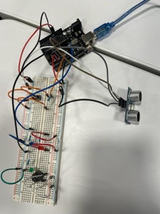
These are the instructions to build our project. There are many different ways to follow the instructions and get a working project, it is important to understand how a breadboard works and the rules of each component. Also, it is not the location of the wires that is important, but rather where they are in comparison to the components, or the code provided.
*How the breadboard works: A bread board is used to easily connect wires and components together temporarily. There are metal plates underneath the holes that connect the holes in rows or columns together. Holes ABCDE are connected in each row by a metal plate, and holes FGHI and J are connected in each row by a metal plate. The entire positive column is connected across the entire column on both sides of the breadboard. This is the same for negative. *
-For all instructions, the color of wire does not necessarily matter but it can be helpful in determining what each wire connects to. You can choose to ignore the wire colors in the instructions.
-General Troubleshooting tips:
- If the device doesn't work, make sure wires are fully connecting and they are in the correct place.
Supplies
- 1 Arduino UNO R3 Controller Board
- 1 Ultrasonic Sensor
- 1 Green LED
- 1 Red LED
- 1 Blue LED
- 1 Active Buzzer (not passive buzzer)
- 1 Button
- 4 220 Ohm Resistors
- 3 short Red Wires
- 1 short Blue Wire
- 1 short Green Wire
- 2 short White Wires
- 4 short Orange Wires
- 1 short Black Wire
- 1 medium Black Wire
- 1 long Black Wire
- 1 medium Red Wire
- 1 Black Female-to-Male Dupont Wire
- 1 Grey Female-to-Male Dupont Wire
- 1 White Female-to-Male Dupont Wire
- 1 Brown Female-to-Male Dupont Wire
Step 1: Adding Button

Materials needed for step 1:
- 4 short Orange Wires
- 3 short Red Wires
- 1 short Black Wire
- 1 long Black Wire
- Button
- 2 220 Ohm Resistors
Breadboard and Arduino Directions:
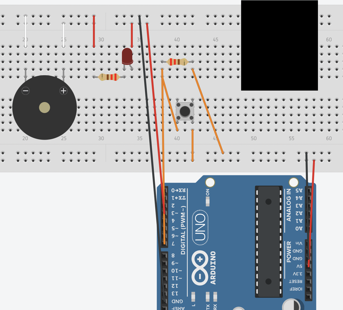
1) Place the button on the breadboard. Exact location does not matter, but it is important to remember how the wiring in the board works as explained in the introduction for the remainder of the steps.
2) Place first resistor (the one above the button in the picture).
3) Add the 4 orange wires as shown in the picture. For the orange wire connecting to the Arduino, make sure it inserts into the slot labeled 7.
4) Place the red LED. Exact placement in relation to the button does not matter, but again, it does matter for future steps.
5)Add the resistor for the LED. Be sure to have the resistor connect to the NEGATIVE side of the LED (you can determine this because the shorter wire connected to the LED is negative)
6) Add a red wire that connects the LED to the positive power strip closest to it. Do the same for the end of the resistor furthest way from the LED, except connect it to the negative column. Connect a long red wire to the positive column that the red LED is connected to and put it into digital pin 3 in the Arduino.
7) Add the short black wire (grounding wire) and the last short red wire. Make sure the black wire connects to the GND (right hand side) on the Arduino and the red wire connects to the 5V slot.
8) Add medium black wire as shown going from the top of the breadboard to the grounding slot on the left.
Full Code for this step:
int buttonState = 0;  // defining variables

int startStopwatchTime; // defining variables for future steps

int currentStopwatchTime; // defining variables for future steps

void setup()

{

  pinMode(7, INPUT);  // Button input is in 7

  pinMode(3, OUTPUT); // LED output in 3


}

void loop()

{

  buttonState = digitalRead(4); // defining variables

  if (buttonState == HIGH)  // If the button is pressed

  {

    digitalWrite(3, HIGH);  // If the button is pressed, the LED turns on

  } else

  {

    digitalWrite(3, LOW); // If the button is not pressed, the LED does not turn on

  }

}
*Troubleshooting with this step:
- If the buzzer does not make a loud sound, it may be the passive buzzer rather than the active buzzer
Step 2: Add Buzzer
Materials needed:
- Active Buzzer
- 2 short White Wires
1) Place Buzzer (the buzzer in your Elegoo kit will be smaller than the one shown in the image)
2) Place two white wires as shown by the image. Because the buzzer is larger in the image the white wires will not be the same distance away on your breadboard. The point of these white wires is that the positive side of the buzzer connects to the positive column on the breadboard and the negative side connects to the negative column on the breadboard.
Code:
int buttonState = 0;  // Defining variables (in previous step)
int startStopwatchTime; // Defining variables (in previous step)
int currentStopwatchTime; // Defining variables (in previous step)
void setup()
{
  pinMode(7, INPUT); // Button is in input 7 (in previous step)
  pinMode(3, OUTPUT);

}
void loop()
{
  buttonState = digitalRead(); // defining button variable
  if (buttonState == HIGH) {
    startStopwatchTime = millis();  // If button is pressed, countdown starts
  } else {

  }
  currentStopwatchTime = millis() - startStopwatchTime; // defining variables   if (( currentStopwatchTime >= 5000) & (currentStopwatchTime <= 8000))
  {
    digitalWrite(3, HIGH); // High input if stopwatch is between 5 and 8 seconds
  } else {
    digitalWrite(3, LOW); // Low input if stopwatch is between 5 and 8 seconds
  }
}
Step 3: Add Ultrasonic Sensor and Two Additional LEDs

Materials needed:
- 1 Ultrasonic Sensor
- 1 Green LED
- 1 Blue LED
- 2 220 Ohm Resistors
- 1 short Blue Wire
- 1 short Green Wire
- 1 long Black Wire
- 1 Black Female-to-Male Dupont Wire
- 1 Grey Female-to-Male Dupont Wire
- 1 White Female-to-Male Dupont Wire
- 1 Brown Female-to-Male Dupont Wire
Directions:
Ultrasonic Sensor
1) Take the black Female-to-Male Dupont wire from the GND on the ultrasonic sensor to the top, negative column on the breadboard
2) Take the white Female-to-Male Dupont wire from the Ucc on the ultrasonic sensor to the bottom, negative column on the breadboard
3)Take the grey Female-to-Male Dupont wire from the Echo on the ultrasonic sensor to the ~5 on the Arduino Board
4) Take the brown Female-to-Male Dupont wire from the Trig on the ultrasonic sensor to the ~6 on the Arduino board
LEDS
Blue LED
1) place the blue LED and one of the 220 Ohm resistors to the breadboard as shown.
2) connect the short blue wire from the negative side of the LED to the top negative column on the breadboard as shown in the image
3) connect the long blue wire from the resistor to the 12 slot on the Arduino as shown in the image
Green LED
1) place the green LED and one of the 220 Ohm resistors to the breadboard as shown.
2) connect the short green wire from the negative side of the LED to the top negative column on the breadboard as shown in the image
3) connect the long black wire (no long green wire in Elegoo kit) from the resistor to the 12 slot on the Arduino as shown in the image.
4) the blue light does not turn on with the code provided. How can you change the code to get the light to turn on?
Full Code (with some things you need to add):
#define echoPin 5 // attach pin D2 Arduino to pin Echo of HC-SR04
#define trigPin 6 //attach pin D3 Arduino to pin Trig of HC-SR04

// defines variables
long duration; // variable for the duration of sound wave travel
int distance; // variable for the distance measurement
int buttonState = 7; // defining button
const int buzzer = 3; // defining buzzer
const int trigger = 6;  // defining sensor
const int echo = 5; // defining sensor
int startStopwatchTime; // defining variables
int currentStopwatchTime; // defining variables
int sensed; //defining variables
const int blueWarningLight = 12; // defining blue light
const int greenLight = 10; // defining green light


void setup()
{
  pinMode(7, INPUT); //sets 7 as an input
  pinMode(12, OUTPUT); // sets 2 as an output
  pinMode(10, OUTPUT); // sets 10 as an output
  pinMode(3, OUTPUT); // sets 3 as an output
  pinMode(trigPin, OUTPUT); // Sets the trigPin as an OUTPUT
  pinMode(echoPin, INPUT); // Sets the echoPin as an INPUT
}

void loop()
{
  buttonState = digitalRead(7); // read the state of the pushbutton value
  digitalWrite(trigPin, LOW);
  delayMicroseconds(2);
  digitalWrite(trigPin, HIGH); // check if pushbutton is pressed.  if it is, the buttonState is HIGH
  delayMicroseconds(10);  // Sets the trigPin HIGH (ACTIVE) for 10 microseconds
  digitalWrite(trigPin, LOW);
  duration = pulseIn(echoPin, HIGH);  // Reads the echoPin, returns the sound wave travel time in microseconds
  distance = duration * 0.034 / 2; // Calculating distace by using Speed of sound wave divided by 2 (go and back)

  if (distance <= 5) {
    sensed = true;  // turn LED on
    digitalWrite(greenLight, HIGH);
  }
  if (buttonState == HIGH) {
    sensed = false; // turn LED on
    digitalWrite(3, LOW);
    startStopwatchTime = millis();
    digitalWrite(greenLight, LOW);
  } else {

  }
  currentStopwatchTime = millis() - startStopwatchTime;
  if ((( currentStopwatchTime >= 5000) & (currentStopwatchTime <= 7000)) & (sensed == false)) {
    digitalWrite(3, HIGH);  // turn LED on

  } else {
    digitalWrite(3, LOW); // turn LED off

  }
  if ((( currentStopwatchTime >= 3000) & (currentStopwatchTime <= 5000)) & (sensed == false)) {
    // turn LED on
       // Using the lines above, try to figure out how to get the warning light to turn on

  } else {
    // Using the lines above, try to figure out how to get the warning light to turn off
  }
}
Step 4: Additional Challenge Problems
1) Try change the interval at which the lights and buzzer goes off
