

Introduction: Arduino Uno/Leonardo Keyboard Macro Box


The parts you need to make the keyboard macro box are:
Electronics:
- Arduino Uno or an Arduino Leonardo
https://store.arduino.cc/arduino-uno-rev3
- Momentary push buttons (I used 15 in my design)
https://www.ebay.co.uk/itm/16mm-Round-Metal-Push-B...
- Jumper Wires, one for each button, power and ground pins.
https://www.ebay.co.uk/itm/40-pcs-Dupont-Cables-M-...
- A Resistor (I used a Red, Red, Brown also known as a 220 ohm resistor)
- Strip board/Breadboard
- Soldering iron and solder.
Optional Electronics:
- LED (External box power LED)
- A Resistor (I used a 180 ohm resistor)
Housing Box:
- 6mm MDF (minimum 32cm x 24cm)
- Handsaw/Jigsaw for cutting the pieces.
- Wood Glue.
- Varnish and a brush. (I used antique pine and gave my box two coats.
- 5mm drill bit to drill a LED hole.
- 10mm drill bit to drill wire hole.
- 16mm drill bit to drill button holes.
- Double cut file. (Half-round and Rat tail)
- Sand paper (120 grit)
Step 1: Building the Housing


You can make a cardboard housing if you are not good with tools, or for a starting prototype box. I am not the best with tools, but I am going to make a wooden box soon anyway, so this was good practice for that next project.
If you decide to make a wooden housing like I did, you will need tools. I glued my box together, so I eliminated the need for nails or screws.
Cutting:
The image above has the dimension for the box size I made, all numbers are centimeters. The larger pieces are the bottom and the top, the piece with the grid on is the top, I used a grid to figure out the center of each button placement.
The left and right pieces are the two slanted pieces, the back piece is the taller of the two remaining pieces, leaving the front piece as the remaining piece on the board.
The wood can be cut with a hand saw, jigsaw or a band saw if you have one at hand. I did it with a hand saw. Sand any cut or sharp edges after you have cut all the pieces. Also sand after drilling.
Drilling:
Then I used the 16mm drill bit to drill the hole for the buttons, try to keep the drill perfectly straight if you don't have a drill press to guide the drill perfectly.
I don't have a drill press so I had to do it by hand, a couple were not straight but a a half-round file was big enough, to fit in and smooth the inside out. I did the same file method once I varnished the top as varnish inside the button holes will stop them from sitting properly.
With the button holes drilled, I place the buttons in to see how it would look, if the buttons don't fit, don't force them in, file the hole with the half-round file then try and fit it in again. My wood was too thick to use the screws on the buttons, so I hot glued mine in place once the circuit was constructed, but more on that in the electronic section.
On my design I used a 5mm drill bit to drill a LED hole into the right side, the LED does not go all the way through because of the thickness of the wood, but it is bright enough that you can tell it is on without looking directly at it. Then on the left I made a 10mm hole then extended it with a rat tail file, to make way for the arduino power cable. If you are using the Leonardo, you should be able to make this hole smaller as the Leonardo uses a micro USB for power where as the Uno uses a USB type B. Just test the wire in between filing so you can get the wire through and back without too much force.
My Uno came with a plastic support tray that I use to hold my board inside the box, to figure out where this will go inside the box, I marked a line the thickness of the wood on the bottom of the box, so for my box it was 6mm from the back. I put the arduino tray against this line centered, then pencil marked dots where the plastic tray holes are. Then hammer some small nails in to hold the tray in place inside.
I used nails from cable clips, you want them long enough to go through the wood and be a pin for the board support tray to hold onto, but not too long that they will stab you or short out your circuit, the nail heads under the board might make the box not sit flat on your desk, some small rubber feet will help stabilize the box, I didn't add these to my box as my box sits on some papers and they stabilize it enough for me.
Gluing:
With all the holes drilled, it is time to start gluing the box together, on the back of the top I measured in the thickness of the wood, so for my box it was 6mm on each side and drew a box, then using this box I glued three off cut pieces inside the box I drew, one on either side and one of the bottom, this is to hold the lid of the box in place, once all the wires are in. This can be seen on the internal picture that looks at the button wiring. Make sure there is no dust or sawdust on the wood before you glue, as it can effect the strength of the glue once dry.
Do a dry run to make sure all the piece of the bottom half fit together correctly first.
With the lid supports drying to one side, I applied a thin layer of wood glue on each joining piece of wood. starting with the back piece, gluing it to the bottom panel, I then did the two side panels, to the back piece and bottom and finally the front to the bottom and the two side pieces, with the glue still wet you can move them around to get them perfectly placed. If you are new to wood gluing you can glue one piece at a time to make sure they are positioned perfectly, but I prefer to do it all in one so I know they will all be in place relative to each other. The glue will take about 20-30 minutes to dry.
Once the glue has dried, place the lid on to see if it fits, my inside off cuts that hold the lid in place, were a bit too far over, so I filed the outer edges of them till the box fit on perfectly. You can also see if the board support tray will fit inside, if your nails are out of place, you can tap them back through and move them over, you can either leave the holes as they wont be seen, or you can fill in the hole with wood filler and sand it smooth once the filler is dry.
Varnishing:
Once the glue has dried, you can move onto varnishing. Before varnishing the wood, give all parts you are going to paint a quick sanding. I used 120 grit sand paper. Make sure all saw dust is off the wood, before you apply the varnish, to make sure the varnish will stick. I varnished my box all in the same direction, to give it an even coat. I also gave the inside of the box one coat which is not necessary as it wont be seen. If the bottom wont be seen that also does not need a coat.
Varnish will dry at different rates, but I left mine for a couple of hours to make sure it was fully dry. Once the varnish is fully dry, you will want to sand down all varnished surfaces, then give it another coat. You can repeat this step again to give it a third coat, the more coats the darker the varnish will look when dries. I stuck to two coats as it looked good enough to me.
You will need to wipe any varnish out of the LED hole, cable hole and button holes as the varnish can block the hole up. If you can't get it all out, you can just file the holes again once the varnish is dry. Varnish inside the box can also stop the lid from sitting nicely, so you will need to file away any varnish that has dripped down into the box as well.
With the box glued and varnished, I put the buttons back in and put it to one side to work on the electronics.
Step 2: Electronics

Circuit Diagram:
The circuit diagram above is a simplified version of what mine is. But adding more buttons is simple, you just join them onto the same ground line as the others, then give each button it's own pin, analog pins can also be used as digital pins, my macro box uses, A0, A1 and A2 for the last three buttons.
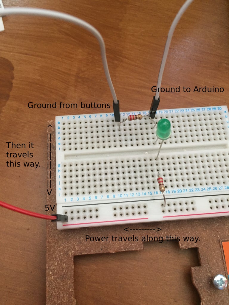
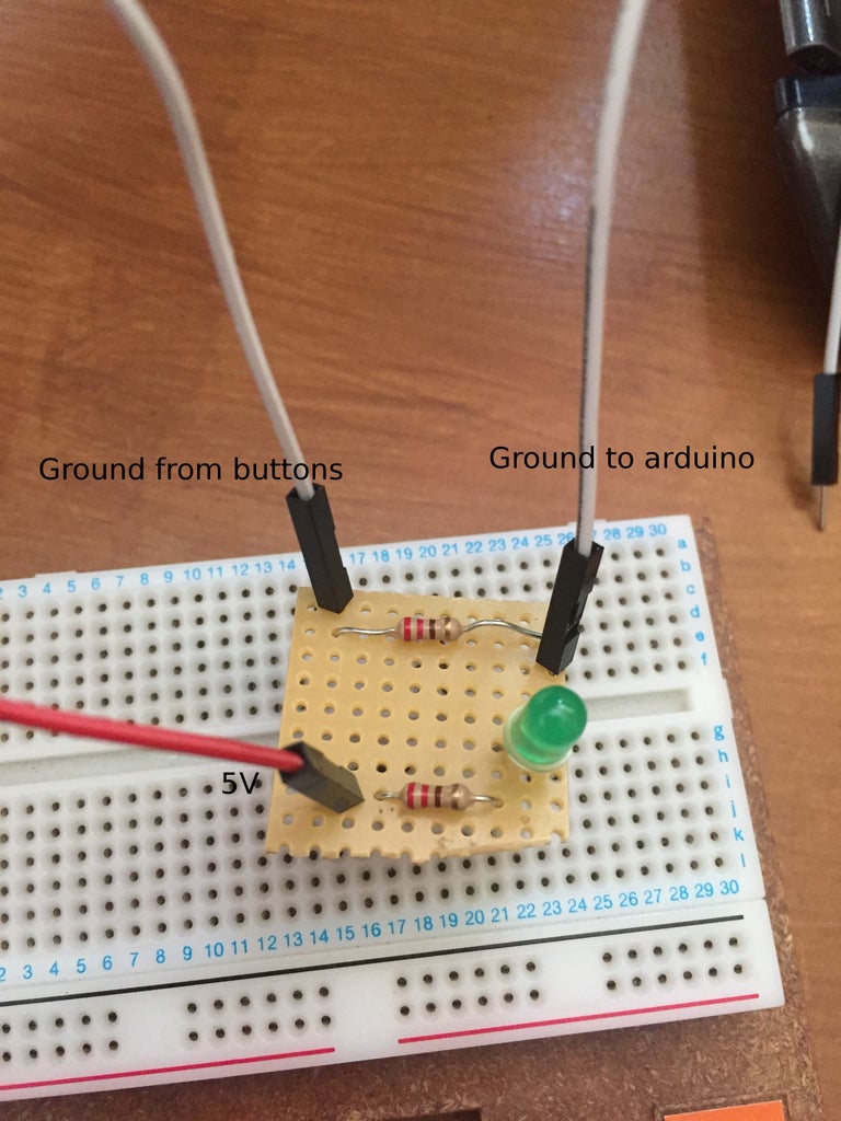
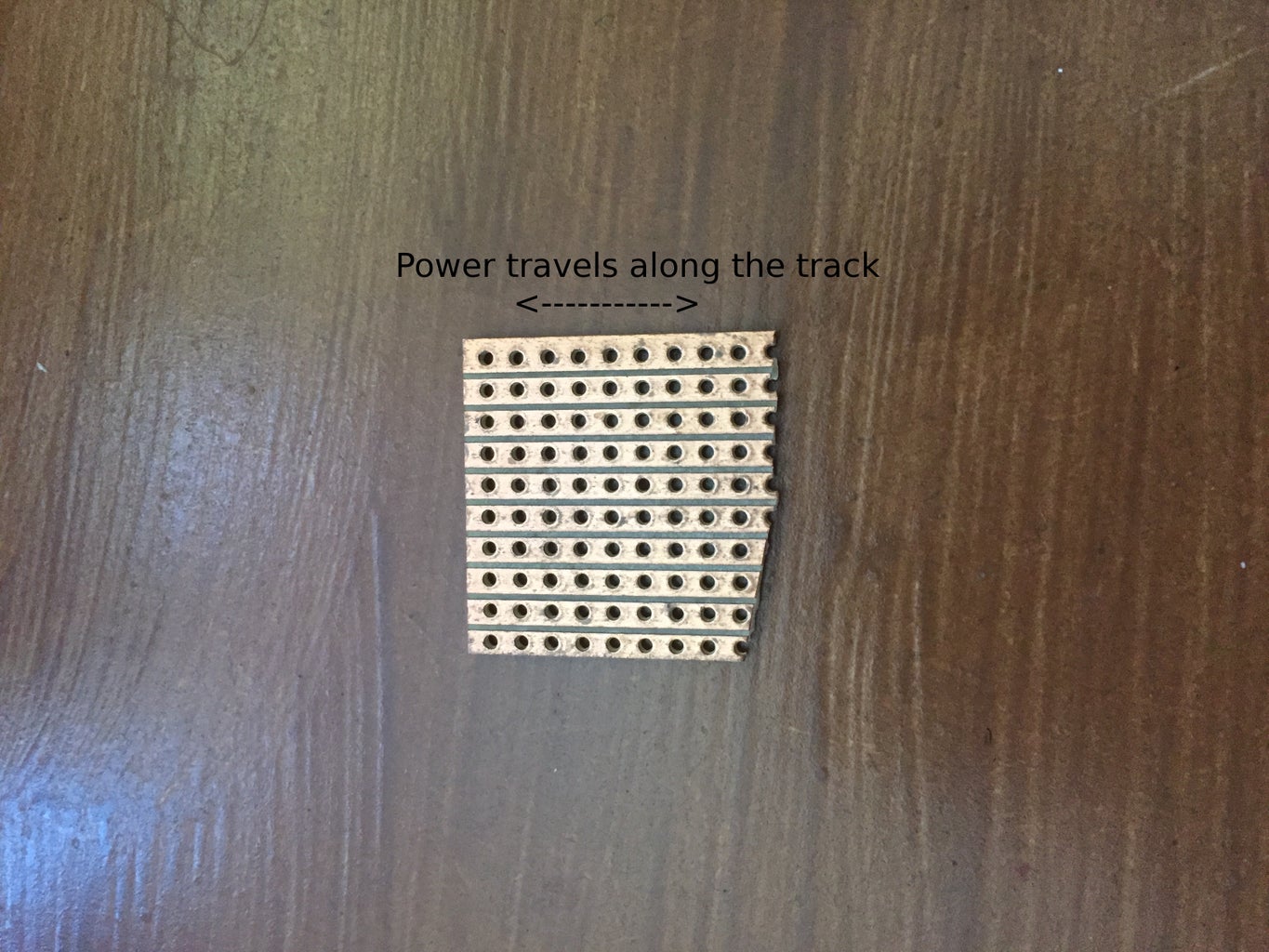
There is also some pictures to show how a circuit would be made on both the breadboard and strip board, with notes on how power flow in each different board types. They can both be made more compact, they are just as an example.
The pin layout is the same for the Uno and the Leonardo, so this circuit diagram should work with a Leonardo, the only difference with the Leonardo will be the code.
I designed my strip board to be in two half's, but they are connected together with a ground wire, but they could be in one piece or you can build it with a breadboard. I wanted the LED and resistor to be closer to the hole, I could have soldered the LED to a couple of wires instead. You could also use two ground pins, one ground pin for the button half and the other for the LED.
LED Circuit:
The resistor before the LED will help stop it from receiving a current over load.
When building the circuit the LED has two legs an anode which is positive, and a cathode which is negative, you can tell the difference as the LED has one leg longer than the other, the longer leg is the positive anode. An LED is just a diode that emits light, so if you put the LED in the circuit backwards, the power wont flow and the LED wont light up.
For the LED circuit it goes, 5V power to resistor, which can go into the circuit either way, it has no polarity. Then into the LED anode, out the LED cathode and into the ground pin.
Button Circuit:
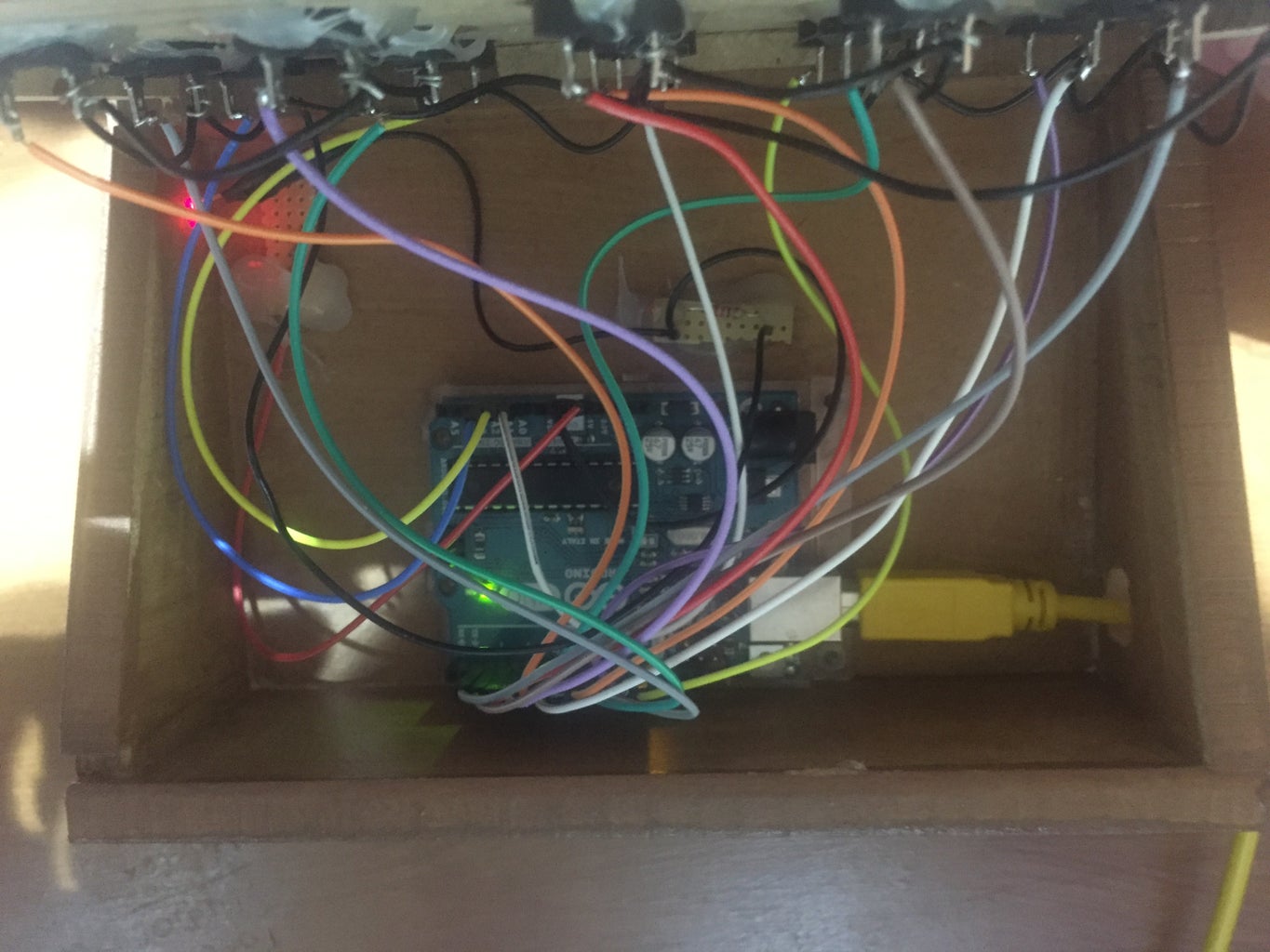
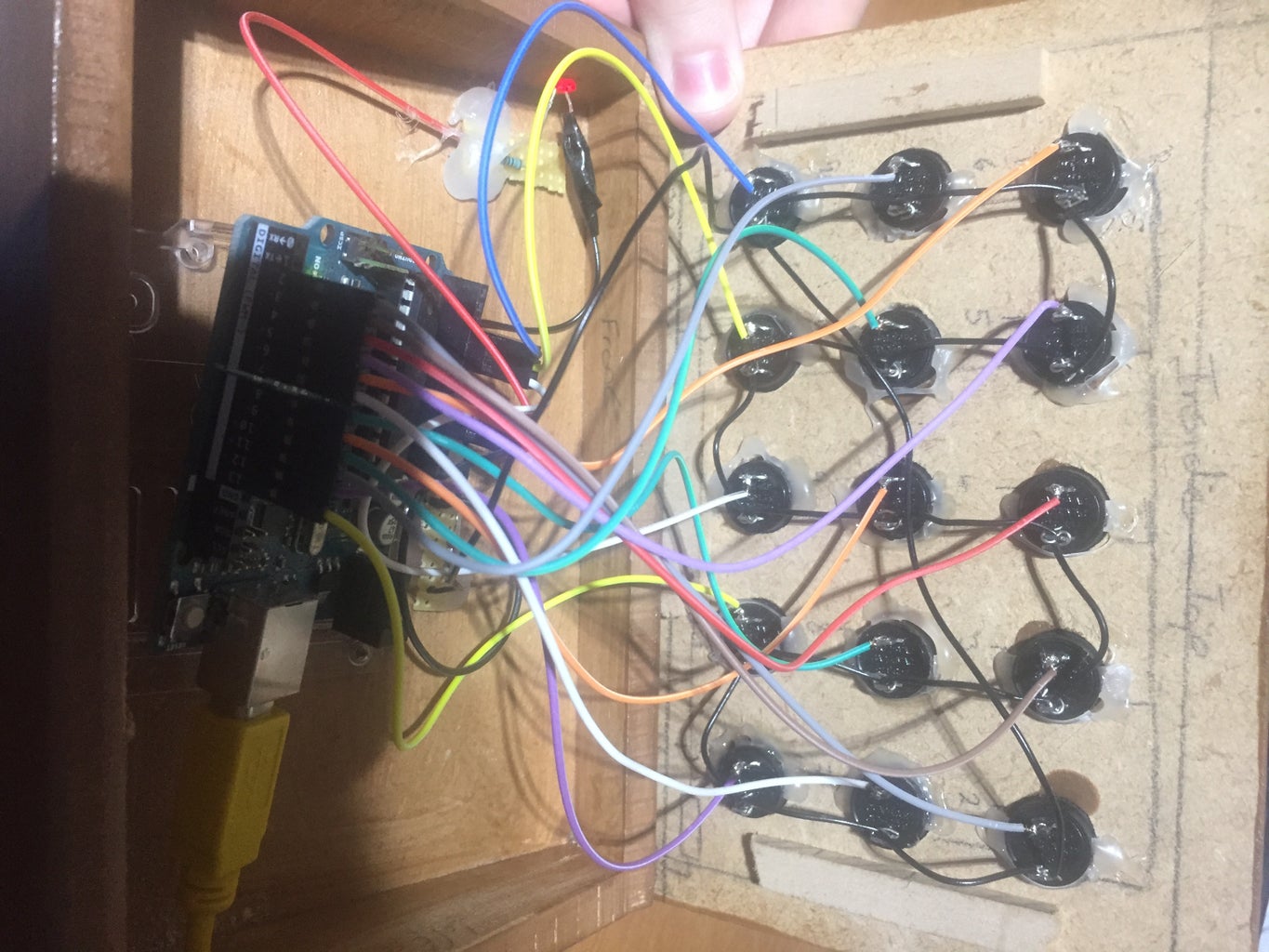
The buttons are placed into the holes with the pins lined up for easy wiring, then hot glued into place, I used a spot of hot glue on the top and bottom of each button. The ground wires were connected first, connect one pin from each button together, I made a winding pattern, then connected the bottom left button to the top right, this can be seen on the picture. The bottom left button was then connected to the strip board.
Next was to solder the resistor and other half of the ground wire to the strip board, as well as the ground wire from the LED circuit.
I cut the female side off of the jumper wires, stripped a bit of the shielding and twisted them around the other pin on each of the buttons. Once each button had a wire twisted to it, I went over and soldered every pin of the buttons, make sure not to hold the soldering iron on the button pins for too long, as the buttons will start to melt.
That is the circuit building done, before you plug all the pins in and close the box up, we need to code the Arduino.
For the coding I will split it into two halves, one will be for arduino
Uno and the other for arduino Leonardo, there are slight difference in code and with the Uno you will need a firmware update to use it like a Leonardo.
Step 3: Arduino Uno Coding

Coding:
The code for the Uno is below, I will go through it step by step, so you know what each part of the code does, in case you want to make changes, you will know where to make the changes. You will need to make changes with hot key names and key codes.
So to start off the code we need to define the keys you are going to use, you do this by writing #define key name KeyID. In my code I have used the CTRL key and function keys. The key ID corresponds to the keys on your keyboard, below is a link that you can use to find specific key codes, it is on page 53 down. It is the left most number, the usage ID (Dec).
http://www.usb.org/developers/hidpage/Hut1_12v2.pd...
https://www.usb.org/sites/default/files/documents/hut1_12v2.pdf
Once you have set all that up, you will need a buffer. A buffer is used to store keyboard presses to the RAM until you press enter to tell your CPU to execute the press command, this is to help stop timing errors and mistypes. We set the buffer in a unsigned int of 8 bits of length, so it will be a 8 int integer.
Next we need to define the pin numbers we are using, if you want to attach LED's to your board that turn on when you press buttons, you will also need to assign the pins used for them. But it is a simple line of code you write it like #define variable name pin number.
Next we will need a base state that every button will be until it is pressed, so here we set an integer with the name state and the value of 1. This will be used later to tell if a button has been pressed.
Inside the setup section, you will need to begin serial communication with your computer at a baud rate of 9600. This is done by writing Serial.begin(9600);
Once you have communication, you will need to assign the mode of the pins. With the code line. pinMode(pinNumber, modeType); The mode type always has to be in full capitals. Any sensor or button is an INPUT, while any LED or buzzer will be an OUTPUT. If you are adding LED's to your buttons, you will need to assign them as OUTPUT, then in the next section assign them to LOW on start up.
Next we want to assign the starting state of all buttons, and any other pins you may be using. You will do this with digitalWrite(pinName, modeType); Digital write, tells the pin what it needs to be. So you are setting its value.
A short delay breaks the start up code from the loop code, to make sure everything has finished setting up before the code continues running.
The loop is the main bulk of the code, I will go over how one button code section works, as they are all the same except they trigger different buttons.
The button starts off with a HIGH value, as this is what has been set in the setup. When you press the button you switch it's state from a HIGH to a LOW, with HIGH being a 1 and LOW being a 0.
So state = digitalRead(buttonName); This line of code reads the button value, one button at a time to see if a change has occurred, if no change has happened, meaning if you have not pressed the button, the code continues along the loop, but if you change it's state by pressing the button the next line of code triggers.
The next line of code if(state != 1) triggers when the state is not 1 (!= means not equal) so if state is != to 1 because it has been changed to a 0 by the button press, execute the code within the if statement.
Once the if statement is triggered, the codes takes the keyboard keys you assigned and stores them in the RAM buffer this is done with. buf[0] = key name followed by buf[2] = variable name so the primary and secondary hot key buttons, so in my code case it would be CTRL + F6 for the first button.
Next the Serial.write(buf, 8); writes the buffer command to the serial, which sends it to the computers CPU to be processed. Which triggers the button presses. So buf[0] and buf[2] hold the keys you want to use at the same time, then the Serial.write sends them to the CPU at the same time, acting like pressing two keys at once.
releaseKey(); is a method that is located under the loop code, after the Serial.write command has been sent this method triggers, which will set the buf[0] and buf[2] to 0 and then sending the same Serial.write command again to push it to the CPU. Once the serial.write has been sent a delay(200); which is a delay of 1/5th of a second to allow the computer to reset the variables. I tried turning this down to 100 before but as I released the button it triggered again. This delay give you enough time to release the button as the code resets. You can tinker and mess with this number to get it perfect for your macro box.
That is the code needed to get your macro box working, but we are not quite finished yet, next we will have to upload and get the Uno working like a keyboard.
//Define buttons used.
#define KEY_LEFT_CTRL 1

#define KEY_F6 63 //Button 1
#define KEY_F7 64 //Button 2
#define KEY_F8 65 //Button 3
#define KEY_F13 104 //Button 4
#define KEY_F14 105 //Button 5
#define KEY_F15 106 //Button 6
#define KEY_F16 107 //Button 7
#define KEY_F17 108 //Button 8
#define KEY_F18 109 //Button 9
#define KEY_F19 110 //Button 10
#define KEY_F20 111 //Button 11
#define KEY_F21 112 //Button 12
#define KEY_F22 113 //Button 13
#define KEY_F23 114 //Button 14
#define KEY_F24 115 //Button 15

uint8_t buf[8] = {0}; //Keyboard timing buffer.

//Define pins used.
#define BUTTON_1 2
#define BUTTON_2 3
#define BUTTON_3 4
#define BUTTON_4 5
#define BUTTON_5 6
#define BUTTON_6 7
#define BUTTON_7 8
#define BUTTON_8 9
#define BUTTON_9 10
#define BUTTON_10 11
#define BUTTON_11 12
#define BUTTON_12 13
#define BUTTON_13 A0
#define BUTTON_14 A1
#define BUTTON_15 A2

int state = 1; //Base state for reference.

void setup()
{
  Serial.begin(9600); //Baud rate for keyboard.

  //Define the pinMode for each pin.
  pinMode(2, INPUT);
  pinMode(3, INPUT);
  pinMode(4, INPUT);
  pinMode(5, INPUT);
  pinMode(6, INPUT);
  pinMode(7, INPUT);
  pinMode(8, INPUT);
  pinMode(9, INPUT);
  pinMode(10, INPUT);
  pinMode(11, INPUT);
  pinMode(12, INPUT);
  pinMode(13, INPUT);
  pinMode(A0, INPUT);
  pinMode(A1, INPUT);
  pinMode(A2, INPUT);

  //Sets the starting value of each pin, on start up.
  digitalWrite(BUTTON_1, HIGH);
  digitalWrite(BUTTON_2, HIGH);
  digitalWrite(BUTTON_3, HIGH);
  digitalWrite(BUTTON_4, HIGH);
  digitalWrite(BUTTON_5, HIGH);
  digitalWrite(BUTTON_6, HIGH);
  digitalWrite(BUTTON_7, HIGH);
  digitalWrite(BUTTON_8, HIGH);
  digitalWrite(BUTTON_9, HIGH);
  digitalWrite(BUTTON_10, HIGH);
  digitalWrite(BUTTON_11, HIGH);
  digitalWrite(BUTTON_12, HIGH);
  digitalWrite(BUTTON_13, HIGH);
  digitalWrite(BUTTON_14, HIGH);
  digitalWrite(BUTTON_15, HIGH);

  delay(200); //Wait before continuing on with the code.
}

void loop()
{
  state = digitalRead(BUTTON_1);
  if(state != 1)
  {
    buf[0] = KEY_LEFT_CTRL; //Presses ctrl key.
    buf[2] = KEY_F6; //Presses F6 key.
    Serial.write(buf, 8); //Sends Keypress.
    releaseKey(); //Calls the releaseKey method.
  }

  state = digitalRead(BUTTON_2);
  if(state != 1)
  {
    buf[0] = KEY_LEFT_CTRL; //Presses ctrl key.
    buf[2] = KEY_F7; //Presses the F7 key.
    Serial.write(buf, 8); //Sends Keypress.
    releaseKey(); //Calls the releaseKey method.
  }

  state = digitalRead(BUTTON_3);
  if(state != 1)
  {
    buf[0] = KEY_LEFT_CTRL; // Presses ctrl key.
    buf[2] = KEY_F8; //Presses the F8 key.
    Serial.write(buf, 8); //Sends Keypress.
    releaseKey(); //Calls the releaseKey method.
  }

  state = digitalRead(BUTTON_4);
  if(state != 1)
  {
    buf[0] = KEY_LEFT_CTRL; //Presses ctrl key.
    buf[2] = KEY_F13; //Presses the F13 key.
    Serial.write(buf, 8); //Sends Keypress.
    releaseKey(); //Calls the releaseKey method.
  }

  state = digitalRead(BUTTON_5);
  if(state != 1)
  {
    buf[0] = KEY_LEFT_CTRL; //Presses ctrl key.
    buf[2] = KEY_F14; //Presses the F14 key.
    Serial.write(buf, 8); //Sends Keypress.
    releaseKey(); //Calls the releaseKey method.
  }

  state = digitalRead(BUTTON_6);
  if(state != 1)
  {
    buf[0] = KEY_LEFT_CTRL; //Presses ctrl key.
    buf[2] = KEY_F15; //Presses the F15 key.
    Serial.write(buf, 8); //Sends Keypress.
    releaseKey(); //Calls the releaseKey method.
  }

  state = digitalRead(BUTTON_7);
  if(state != 1)
  {
    buf[0] = KEY_LEFT_CTRL; //Presses ctrl key.
    buf[2] = KEY_F16; //Presses the F16 key.
    Serial.write(buf, 8); //Sends Keypress.
    releaseKey(); //Calls the releaseKey method.
  }

  state = digitalRead(BUTTON_8);
  if(state != 1)
  {
    buf[0] = KEY_LEFT_CTRL; //Presses ctrl key.
    buf[2] = KEY_F17; //Presses the F17 key.
    Serial.write(buf, 8); //Sends Keypress.
    releaseKey(); //Calls the releaseKey method.
  }

  state = digitalRead(BUTTON_9);
  if(state != 1)
  {
    buf[0] = KEY_LEFT_CTRL; //Presses ctrl key.
    buf[2] = KEY_F18; //Presses the F18 key.
    Serial.write(buf, 8); //Sends Keypress.
    releaseKey(); //Calls the releaseKey method.
  }

  state = digitalRead(BUTTON_10);
  if(state != 1)
  {
    buf[0] = KEY_LEFT_CTRL; //Presses ctrl key.
    buf[2] = KEY_F19; //Presses the F19 key.
    Serial.write(buf, 8); //Sends Keypress.
    releaseKey(); //Calls the releaseKey method.
  }

  state = digitalRead(BUTTON_11);
  if(state != 1)
  {
    buf[0] = KEY_LEFT_CTRL; //Presses ctrl key.
    buf[2] = KEY_F20; //Presses the F20 key.
    Serial.write(buf, 8); //Sends Keypress.
    releaseKey(); //Calls the releaseKey method.
  }

  state = digitalRead(BUTTON_12);
  if(state != 1)
  {
    buf[0] = KEY_LEFT_CTRL; //Presses ctrl key.
    buf[2] = KEY_F21; //Presses the F21 key.
    Serial.write(buf, 8); //Sends Keypress.
    releaseKey(); //Calls the releaseKey method.
  }

  state = digitalRead(BUTTON_13);
  if(state != 1)
  {
    buf[0] = KEY_LEFT_CTRL; //Presses ctrl key.
    buf[2] = KEY_F22; //Presses the F22 key.
    Serial.write(buf, 8); //Sends Keypress.
    releaseKey(); //Calls the releaseKey method.
  }

  state = digitalRead(BUTTON_14);
  if(state != 1)
  {
    buf[0] = KEY_LEFT_CTRL; //Presses ctrl key.
    buf[2] = KEY_F23; //Presses the F23 Key.
    Serial.write(buf, 8); //Sends Keypress.
    releaseKey(); //Calls the releaseKey method.
  }

  state = digitalRead(BUTTON_15);
  if(state != 1)
  {
    buf[0] = KEY_LEFT_CTRL; //Presses ctrl key.
    buf[2] = KEY_F24; //Presses the F24 key.
    Serial.write(buf, 8); //Sends Keypress.
    releaseKey(); //Calls the releaseKey method.
  }
}

//Used to release keys.
void releaseKey()
{
  buf[0] = 0; //Resets number.
  buf[2] = 0; //Resets number.
  Serial.write(buf, 8); //Release key.
  delay(200);
}
Uploading:
Uploading the code to your Arduino is as easy as plugging your board in, pressing the tools button at the top of the screen, going down to board, selecting the board you are using and then going to port selecting the port your board is connected to.
Verify the code by pressing the tick under the file button, then once it is verified upload it with the button next to it, that is an arrow pointing right.
Once it says uploaded, your board is ready to go, onto the next phase.
Firmware:
To get your Uno to work like a keyboard it will need a firm ware update. To update the firmware you will need a piece of software and a hex file.
http://www.microchip.com/developmenttools/ProductD...
https://github.com/SyllogismRXS/syllo-arduino
Install Atmel flip which will allow you to put the arduino-keyboard-0.3.hex file onto the arduino.
Arduino to Keyboard: Once Atmel is installed and your board is plugged in, load Atmel up and click on the computer chip icon below the file button, select the processor of the board you are using. In my case it was a ATmega16U2. Then click the icon next to that one and click USB to begin communication via USB, if you get an error while pressing this button you will need to take an extra couple of paragraphs.
If you get the error before the open button shows up, while opening communications with your arduino. You will need to force a driver update before you continue, to do this you will need to open device management, the easiest way to get to the device management on windows 10 is to right click the windows button in the bottom left of the desktop and scroll up to device management.
With the device management open you will need to find your arduino, it might be displayed as an unknown device or just as a USB device, find it and right click it, open the properties window. In the general section of the device there should be a update drivers button. The drivers are located with the Atmel file that you installed, they are in Atmel/Flip 3.4.7/usb click the update drivers button and click choose from file, then browse and locate the usb folder. Then open the driver, click next and the driver will get updated. After some time the driver should be installed. You will get a notification when it is installed. Now with the driver installed go back to Atmel, click the same button and click USB again, this time you should get the option to open.
Before you can click the open button you need to short out two pins, on the picture above you will see an arrow pointing at two pins, get a piece of jumper wire and short the two pins closest to the USB port. Once it has been shorted the arduino firmware will be wiped.
Now you can click the open button, the interface of Atmel will be able to be used. Click file Load HEX file and locate the arduino-keyboard-0.3.hex file you downloaded, the other file you have is to turn the arduino back into a normal arduino when you need to update code or use the arduino for another purpose.
Click the Blank Check box and hit run, all lights should go green, if verify goes red. Reload the arduino-keyboard-0.3.hex file and hit run again. It should work the second time. With the code verified, hit the Start Application button, you will hear the window disconnect sound and communication will go off, the .hex was also written to the arduino.
Unplug and plug the arduino back in, it will now be seen to the computer as a keyboard and not an arduino. Below is a paragraph on how to convert the arduino back into an arduino.
Keyboard to Arduino: To get the arduino back to a normal arduino, you need to load Atmel, plug the arduino uno in. Then go to devices and printers, find your arduino which will be called a keyboard. Right click and remove device, with the device removed, go back to Atmel short out the two pins, then open communication via USB. Load the Arduino-usbserial-uno.hex file, make sure all the check boxes are ticked on the left, then hit the Run button, once it has been checked and all the lights are green, if the verify buttons goes red, load the Arduino-usbserial-uno.hex file again, then hit the run button again. With all lights green hit the Start Application button. Once the .hex is uploaded and communication is off, unplug the arduino and plug it back in and it should show up in the devices and printers as an arduino again.
Final Step:
With the code written and the board firmware updated, it is a simple final step of putting the board in the box, connecting all the wires to the correct pins and plugging the board into the computer.
Step 4: Arduino Leonardo Coding
I brought an arduino Leonardo to build this project as I thought, because it works like a USB device it will be easier, to not have to worry about firmware updates. I was wrong, the Leonardo is the hardest arduino board I have worked with so far, my other boards, both Uno and Mega2560 are amazing to work with.
If your board is fresh out of the box with no code on it, this might be the easier option to you. But I uploaded other code to mine to test how it works before I tried to move onto this project code. The process to upload to the board while it has code on. Is very timing based.I will explain this better, below the coding in the upload section.
Code Explanation:
I will go through step by step the code below. To begin with we have a #include "Keyboard.h" this gets access to the arduino keyboard library, this is what most of the code will be based around. The Uno can't access this library even with it's firmware update.
The next step is to define all pins being used, we do this with #define variable name pin number we do this for each pin used. If you set up LED's that light up when a button is pressed, you will also need to assign them pins here.
We declare a state, this will be the base state that the code references, to know if a button has been pressed. It is an int as it is just a basic number, and it is set to be 1 on start up.
Now that everything is defined, we move into the setup portion of the code, We start by setting the mode of each pin, we do this with pinMode(pinNumber, modeType); The mode type always has to be in full capitals. Any sensor or button is an INPUT, while any LED or buzzer is an OUTPUT. If you are adding LED's to your buttons, you will need to assign them as OUTPUT, then in the next section assign them to LOW on start up.
Next we want to assign the starting state of all buttons, and any other pins you may be using. You will do this with digitalWrite(pinName, modeType); Digital write, tells the pin what it needs to be, so you are setting it's value.
To access the arduino keyboard library we need to begin keyboard inputs, we do this with. Keyboard.begin();
A short delay breaks the start up code from the loop code, to make sure everything has finished setting up before the code continues running.
The loop is the main bulk of the code, I will go over how one button code section works, as they are all the same except they trigger different buttons, then I will explain an extra feature that makes a Leonardo better than the Uno.
So state = digitalRead(buttonName); This line of code reads the button value, one button at a time to see if a change has occurred, if no change has happened, meaning if you have not pressed the button, the code continues along the loop, but if you change it's state by pressing the button the next line of code triggers.
The next line of code if(state != 1) triggers when the state is not 1 (!= means not equal) so if state is != to 1 because it has been changed to a 0 by the button press, execute the code within the if statement.
Once the if statement is triggered, the Keyboard.press(KEY_LEFT_CTRL); and Keyboard.press(KEY_F6) activate, this accesses the library and tells the computer what keys to press, if you want to use different keys, use the link below to find out what you need to type in place of KEY_LEFT_CTRL and KEY_F6.
https://www.arduino.cc/reference/en/language/funct...
The delay(200); is there to give you time to release the button, before the arduino tells the CPU to release the key.
Finally the Keyboard.releaseAll(); tells the CPU to release all the keys that you have pressed.
Extra Notes: If you want to use a letter key it will be used like 'V' you can see this in the code below, you can also set a button to print a string with one button press, you do this with the Keyboard.print("Hello World"); so this line of code will print the string inside the " " when the button is pressed. You can do this for words that you type a lot, you can even put in URL's, emails or any other string of text you may need.
#include "Keyboard.h"

//Define pins used.
#define BUTTON_1 2
#define BUTTON_2 3
#define BUTTON_3 4
#define BUTTON_4 5
#define BUTTON_5 6
#define BUTTON_6 7
#define BUTTON_7 8
#define BUTTON_8 9
#define BUTTON_9 10
#define BUTTON_10 11
#define BUTTON_11 12
#define BUTTON_12 13
#define BUTTON_13 A0
#define BUTTON_14 A1
#define BUTTON_15 A2

int state = 1;

void setup()
{
  //Define the pinMode for each pin.
  pinMode(2, INPUT);
  pinMode(3, INPUT);
  pinMode(4, INPUT);
  pinMode(5, INPUT);
  pinMode(6, INPUT);
  pinMode(7, INPUT);
  pinMode(8, INPUT);
  pinMode(9, INPUT);
  pinMode(10, INPUT);
  pinMode(11, INPUT);
  pinMode(12, INPUT);
  pinMode(13, INPUT);
  pinMode(14, INPUT);
  pinMode(15, INPUT);

  //Sets the value of the pin on start up.
  digitalWrite(BUTTON_1, HIGH);
  digitalWrite(BUTTON_2, HIGH);
  digitalWrite(BUTTON_3, HIGH);
  digitalWrite(BUTTON_4, HIGH);
  digitalWrite(BUTTON_5, HIGH);
  digitalWrite(BUTTON_6, HIGH);
  digitalWrite(BUTTON_7, HIGH);
  digitalWrite(BUTTON_8, HIGH);
  digitalWrite(BUTTON_9, HIGH);
  digitalWrite(BUTTON_10, HIGH);
  digitalWrite(BUTTON_11, HIGH);
  digitalWrite(BUTTON_12, HIGH);
  digitalWrite(BUTTON_13, HIGH);
  digitalWrite(BUTTON_14, HIGH);
  digitalWrite(BUTTON_15, HIGH);

  Keyboard.begin(); //Turns the keyboard input on.
  delay(200); //Wait before continuing on with the code.
}

void loop()
{
  state = digitalRead(BUTTON_1);
  if(state != 1)
  {
    Keyboard.press(KEY_LEFT_CTRL); //Presses the CTRL key.
    Keyboard.press('C'); //Presses the C key.
    delay(200);
    Keyboard.releaseAll();
  }

  state = digitalRead(BUTTON_2);
  if(state != 1)
  {
    Keyboard.press(KEY_LEFT_CTRL); //Presses the CTRL key.
    Keyboard.press('V'); //Presses the V key.
    delay(200);
    Keyboard.releaseAll();
  }

  state = digitalRead(BUTTON_3);
  if(state != 1)
  {
    Keyboard.print("Hello World"); //Prints a string message.
    delay(200);
    Keyboard.releaseAll();
  }

  state = digitalRead(BUTTON_4);
  if(state != 1)
  {
    Keyboard.press(KEY_LEFT_CTRL); //Presses the CTRL key.
    Keyboard.press(KEY_F6); //Presses the F6 key.
    delay(200);
    Keyboard.releaseAll();
  }

  state = digitalRead(BUTTON_5);
  if(state != 1)
  {
    Keyboard.press(KEY_LEFT_CTRL); //Presses the CTRL key.
    Keyboard.press(KEY_F7); //Presses the F7 key.
    delay(200);
    Keyboard.releaseAll();
  }

  state = digitalRead(BUTTON_6);
  if(state != 1)
  {
    Keyboard.press(KEY_LEFT_CTRL); //Presses the CTRL key.
    Keyboard.press(KEY_F8); //Presses the F8 key.
    delay(200);
    Keyboard.releaseAll();
  }

  state = digitalRead(BUTTON_7);
  if(state != 1)
  {
    Keyboard.press(KEY_LEFT_CTRL); //Presses the CTRL key.
    Keyboard.press(KEY_F10); //Presses the F10 key.
    delay(200);
    Keyboard.releaseAll();
  }

  state = digitalRead(BUTTON_8);
  if(state != 1)
  {
    Keyboard.press(KEY_LEFT_CTRL); //Presses the CTRL key.
    Keyboard.press(KEY_F11); //Presses the F11 key.
    delay(200);
    Keyboard.releaseAll();
  }

  state = digitalRead(BUTTON_9);
  if(state != 1)
  {
    Keyboard.press(KEY_LEFT_CTRL); //Presses the CTRL key.
    Keyboard.press(KEY_F12); //Presses the F12 key.
    delay(200);
    Keyboard.releaseAll();
  }

  state = digitalRead(BUTTON_10);
  if(state != 1)
  {
    Keyboard.press(KEY_LEFT_SHIFT); //Presses the SHIFT key.
    Keyboard.press(KEY_F6); //Presses the F6 key.
    delay(200);
    Keyboard.releaseAll();
  }

  state = digitalRead(BUTTON_11);
  if(state != 1)
  {
    Keyboard.press(KEY_LEFT_SHIFT); //Presses the SHIFT key.
    Keyboard.press(KEY_F7); //Presses the F7 key.
    delay(200);
    Keyboard.releaseAll();
  }

  state = digitalRead(BUTTON_12);
  if(state != 1)
  {
    Keyboard.press(KEY_LEFT_SHIFT); //Presses the SHIFT key.
    Keyboard.press(KEY_F8); //Presses the F8 key.
    delay(200);
    Keyboard.releaseAll();
  }

  state = digitalRead(BUTTON_13);
  if(state != 1)
  {
    Keyboard.press(KEY_LEFT_SHIFT); //Presses the SHIFT key.
    Keyboard.press(KEY_F10); //Presses the F10 key.
    delay(200);
    Keyboard.releaseAll();
  }

  state = digitalRead(BUTTON_14);
  if(state != 1)
  {
    Keyboard.press(KEY_LEFT_SHIFT); //Presses the SHIFT key.
    Keyboard.press(KEY_F11); //Presses the F11 key.
    delay(200);
    Keyboard.releaseAll();
  }

  state = digitalRead(BUTTON_15);
  if(state != 1)
  {
    Keyboard.press(KEY_LEFT_SHIFT); //Presses the SHIFT key.
    Keyboard.press(KEY_F12); //Presses the F12 key.
    delay(200);
    Keyboard.releaseAll();
  }
}
Uploading:
You need to be in the arduino IDE ready to upload the code, hold the reset button on the Leonardo, as soon as you press it press CTRL + U to upload the new code, as soon as it says uploading in the bottom of the IDE release the reset button on the Leonardo and hope that you got the timing right. If you got the timing right it will upload and display the Done uploading message, if you got it wrong you will get an error message, the timing needs to be perfect. You will need to repeat until you get the code uploaded, took me about 15 tries to begin with. You might need to set the COM port up again. But after some time I managed to do it in a couple of tries.
The reason this is so tricky is because the Leonardo has 2 serial setups. The first is the physical one on the board that all arduino's have, the second is a virtual serial port, when you connect the board to the computer it uses the first to check for new code, then swaps to the second for general operation and code loops. You need to catch the board with the upload sequence while the board is still on the first COM port, as soon as it moves to the second it does not try to look for new code, it just runs what it has.
If you upload to an Leonardo I would recommend, checking your code two or three times before you upload it, to make sure there are no errors, so you don't have to fight your board as much.
Even though uploading to a Leonardo is quite a challenge to begin with, the code is easier than the Uno, even though they are similar in design, the Leonardo takes fewer steps because it takes advantage of the keyboard library.
Step 5: Testing
Typing/Short cuts:
If you set up the buttons to write normal text and not function hot keys, testing can be as easy as going into notepad. Then press a button and see it type, if you set it up to copy text with one button and paste with another, write something up, high light it and test the buttons out.
Or if you are using Keyboard.print("customString"); on your Leonardo, you can see if the string shows correctly when you press the button.
Soundboard:
I set mine up to be used as a sound board, so I wrote this piece of software below, set up sound effects to each button, then set up the hot keys to match the ones I coded into my arduino.
https://fortstudios.itch.io/sound-board
Final Notes:
If you have trouble with any part of the process, don't hesitate to send a message. I will get back to you as soon as possible, to help fix any issues with the tutorial or that you may be having.
Step 6: References
I used a couple other tutorials to help in the building of this project as well general coding knowledge. Below are the links to the videos and pages that helped me.
https://www.instructables.com/id/Arduino-Programma...
So thank you to these people, for the help these videos and tutorial had on the project of building my own macro box.
