

Introduction: Automated Cocktail Drink Machine


Hey guys,
In this instructables I want to show you how to build your own automated mixed-drink maker to satisfy all your liquid (and alcohol ;) )needs.
For a while now, I have been satisfying my thirst and taste-buds with pre-made concentrates from sodastream. The unit allows you to easily carbonate water and add flavoring to it. However, where it exceeds in easy of use, it lacks in quality. After nearly 4 months of research and planning, I can finally say that i have built my own solution that goes above and beyond anything currently on the market. Having gone through all the steps, this project is great for those who want to build a full-tier product, involving both software and hardware. This project has been a great starting point for the exploration of arduino and manufacturing.
With that being said, Follow along to build your own Automated Mixed-Drink Machine..
Take a look at the 3D model below, this is an outline of what the final product should like once your done.
(If you can't see the interactive 3D model below, its probably because you're not using a WebGL - enabled browser, or your using the instructables app))
However, Before we get any further, its a good idea for you to know what you are going to build, so take a look at these wonderful beauty shots. (yes there is a top, but the internals look cool for the photos :D )


Below are GIFs of each station. As the drink is being constructed, it is transported to each station on the a motorized sliding rail. Depending on the recipe, the drink may or may not need to move in different patterns.
Stations Include:
- Automated Mint, Sugar, and Lime Muddle for releasing all the flavors
- Automated Lime Slicer and Dispenser
- Automated Mint and Sugar Dispenser
- Automated Liquid Dispenser
Additionally all these processes are controlled by multiples Arduinos and 10.1" tablet via a Serial Connection. (Refer to coding steps)


WOW!!!!
(This looks even better in real life. If you guys want more photos, please don't hesitate to ask in the comments - i will be happy to upload more :D)
Step 1: Mechanical Parts List
The entire machine was modeled and designed in Fusion 360. Below you can find all the required technical parts and files for the machine.
Standard Hardware Parts:
Most of these parts you can buy at a local hardware store or online from Amazon/Aliexpress:
| Quantity | Description | Link | Price |
|---|---|---|---|
| 4x | 32-35 mm (1") pipe mounting brackets | Bauhaus | 3,50€ |
| 4x | 32-35 mm (1") pipe mounting brackets | Bauhaus | 3,50€ |
| 2x | 74-80 mm (21/2") pipe mounting brackets | Bauhaus | 4,50€ |
| 10x | Square mounting brackets | Bauhaus | 15,00€ |
| 1x | 500mmx1500mmx60mm Styrofoam Panel | Bauhaus | 3,00€ |
Nails, Screws, Nuts, Bolts, and Washers:
| Quantity | Description | Where to buy | Price |
|---|---|---|---|
| 8x | M5x20mm DIN912 cylinderhead screw | local hardware store | - |
| 4x | M5x10mm DIN912 cylinderhead screw | local hardware store | - |
| 6x | M4x20mm DIN912 cylinderhead screw | local hardware store | - |
| 4x | 1.2mmx20mm Steel Nails | local hardware store | - |
| 20x | M3x30mm DIN912 cylinderhead screw | local hardware store | - |
| 10x | M3x25mm DIN912 cylinderhead screw | local hardware store | - |
| 30x | 5mmx15mm Wood Screws | local hardware store | - |
| 20x | 5mmx30mm Wood Screws | local hardware store | - |
| 2x | 30mmx50mm Brass Hinges | local hardware store | - |
| 20x | M3 Nut | local hardware store | - |
| 15x | M5 washer | local hardware store | - |
| 6x | M4 washer | local hardware store | - |
| 30x | M3 washer | local hardware store | - |
Pipes & Rails:
| Quantity | Description | Link | Price |
|---|---|---|---|
| 1x | 20x1000mm round aluminium extrusion | local hardware store | 3,50€ |
| 1x | 15x15x1000 square stainless steel extrusion | local hardware store | 8,80€ |
| 1x | 12x1000mm round aluminium extrusion | local hardware store | 5,80€ |
| 1x | 75mm Y PVC Pipe Fitting | local hardware store | 0,50€ |
| 1x | 75mm T PVC Pipe Fitting | local hardware store | 0,50€ |
| 1x | 75mmx500mm round PVC pipe | local hardware store | 0,75€ |
CNC-Laser-Cut Parts:
All laser cut parts were cut on a BOSS LS-1630 laser cutter. I was able to get access to a laser cutter from a nearby school, but there are more and more maker-shops poping up, and those often have similar equipment. For 3mm Acrylic, power was set to 90 and speed 25. For 5mm Acrylic parts the power was set to 95 and speed 10. These settings seemed to work well - it always cut through the plastic and protective covering without any problems, however depending on your machine these settings will likely need to be changed.
These are the "must-have" laser cut parts - additional laser cut parts from 3mm&5mm acrylic sheets are included in the files, however these only for atheistic purposes.
DXF Files can be found at the bottom of this step
| Quantity | Description | How the part looks like |
|---|---|---|
| 1x | Top Bracket |  |
| 2x | Side Bracket |  |
| 1x | Bottom Slider |  |
| 1x | Copper Backing |  |
| 1x | Wood Bracket |  |
| 1x | Left Panel |  |
| 2x | Top & Bottom Electronic Structure |  |
| 2x | Side Panel Electronic Structure |  |
| 8x | Braces |  |
3D-Printed Parts:
The 3D-Printed parts are made out of PLA with a resolution of 0.1mm. I used a Prusa I3 Mk3 3D printer to print the parts. Total Print time was around 48 hours and used almost 500g of filament at 20% infill.
All the required STL files are available at the end of this step in addition to GrabCAD and Fusion360 Gallery.
| Quantity | Description | How the part looks like |
|---|---|---|
| 1x | Mint Container |  |
| 1x | Sugar Container |  |
| 1x | Mint Auger |  |
| 1x | Sugar Auger |  |

Step 2: Electronics Part List

Below you can find a list of all the electrical and technical parts (and links to the purchased parts). Many of these can be found in pre-made kits from elegoo, such as:
- ELEGOO Mega 2560 Project The Most Complete Starter Kit
- ELEGOO EL-KIT-012 UNO Project Smart Robot Car Kit V 3.0 with UNO R3
I Highly recommend these as they also come with tutorials and other projects for future DIYing! :)
| Quantity | Description | Name on PCB | Link | Price |
|---|---|---|---|---|
| 1x | Arduino Uno R3 | Elegoo Kit | - | |
| 1x | Arduino Mega 2560 | Elegoo Kit | - | |
| 8x | 1k Resistor | Elegoo Kit | - | |
| 1x | 500N, 100mm, Linear Actuator 20mm/s | Bangood | 38$ | |
| 1x | 200N, 200mm, Linear Actuator 50mm/s | Bangood | 45$ | |
| 3x | 5x 60w Peltier Modules | Amazon | 12$ | |
| 1x | 9g Servo Motor | Glass Slider | Elegoo Kit | - |
| 1x | 10.1" Samsung Tablet | - | ||
| 1x | LN298 Motor Driver | Elegoo Kit | - | |
| 50x | M-M BreadBoard Wires | Elegoo Kit | - | |
| 1x | Bread Board | Elegoo Kit | - | |
| 2x | 8 Channel Relay | Amazon | 7$ | |
| 2x | 120mm Fans | - | ||
| 7x | Pumps | - |
Step 3: Build the Base and Drink Cabinet


Here comes the most important part, build the structural frame for all the technical parts. The goal here was to make the entire product look and feel as professional as possible. Using materials such as shiny acrylic, hard PVC sheets and thick dark wood did just that. They provided a feed that resembled the strength and functionality of an industrial appliance, but also emitted a sense of homeliness and luxury.
After all, this is just that, a luxury machine. I mean... Its a cocktail maker with copper sheets just for looks! WOW!
The Process:
First things first, we need to cut each material to its required size. A list of hand drawn dimensions and diagrams can be seen below, but also obtained via the 3D model above and DXF files for each part. (I'll Include those at the end of this step)


Attachments

Step 4: Construct the Mint & Sugar Dispensers


First things first - Print the parts. The 3D-Printed parts are made out of PLA with a resolution of 0.1mm. I used a Prusa I3 Mk3 3D printer to print the parts. I found 20% infill to be the best compromise between strength and filament used.
Below is a cross section of a failed print. Here you can see the internal grid structure that provides the 3D object its strength. I even took this piece and ran over it with a car, it still looks the same. :)

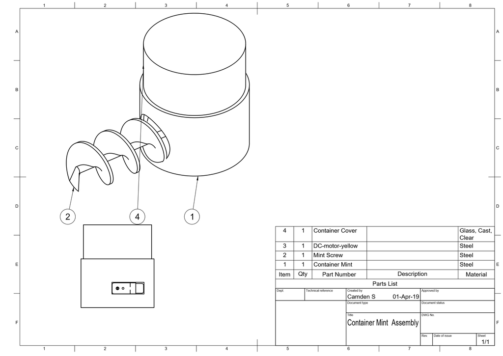
Once you have all your 3D printed parts, its time to clean them up. I used a chisel and pliers to remove all the support structure, and then sanded every surface with 100,200, and 400, grit sand paper. It is important that these parts have a smooth surface as they will be rubbing against each other.
Next, you want to insert your motor into the square cavity (you can see this clearly above). Make sure the shaft lines up with the hollowed out circular hole. the tab of the motor should also fit in the tiny square hole perpendicular to the shaft. Once the motor is in place, use hotglue to secure to the 3D printed structure.
After the glue is dry, take the matching auger and slide it into the container. there is a D shaped mounting bracket at the end of the auger shaft which matches that of the motor, use super glue to attach the two for a strong fit.
Once the product is complete, mint and sugar will fill the large and small containers respectively. The rotating auger/Archimedes screw will transport the material to the T-shaped pipe, where they both fall down the same shaft into the glass.
Using a screw to dose materials allows us to be very accurate (to the gram in my experiments). With this accuracy, we can make the perfect drink!
Step 5: Slider Module (Moves the Glass)


As you can see in the 3D model above, this is the sliding mechanism used to transport the glass between stations (Liquid Fill, Lime Fill, Sugar/Mint Fill, & Linear Actuator Muddle Station)
Parts Needed:
- 15x15mm Square Chrome Pipe
- 12mm Diameter Chrome Pipe
- 9g Continuous Servo Motor
- 70mmx100mmx18mm Dark Wood
Cut the Pipes:
You will need to make adjustments to the side of the Pipe Stock. Below you can find the dimensions and quantity required for each part.
- 430mmx12mm Diameter Chrome Pipe (2x)
- 100x15x15mm Square Chrome Pipe (2x)
- 70x100x18mm Stained Wooden Block (1x)
Adjusting the wooden block:
As shown in the interactive 3D model, underneath you will need to house the 9g servo motor. Using a chisel remove 12(d)x34(w)x40(l) of material. I also found that using a 30-35mm circular drill bit was a fast and easy method to remove the majority of material.
Once the square is removed, using hot-glue, mount the 9g servo motor underneath. The orientation isn't important, but i found it is better to have the side with the cable on it closer to the wall so it doesn't get stuck.
Next, using the mounting brackets that come with the servo, attach them to a circular (20mm Diameter) disk (Laser cut DXF Files). This will be the wheel that provides traction to move the slider.
Once the servo is mounted, Hot glue the wooden block to the two square chrome pipes. Attach the pipes on the two longer sides of the block. Once attached, the entire piece should make a 100x100mm square.
Next slide the two longer 12mm round chrome pipes though the 15x15mm square pipes.
The Slider Is now complete, and can be mounted in a future step!
Step 6: How to Select a Peltier Module

Common thermal management solutions used in electronics applications address cooling objects with heat exchangers and fluid flow. The heat exchanger is typically either the electronic package itself or an extruded or stamped heat sink attached to the package. Air is the most common fluid used in thermal solutions, either with natural convection or propelled by a fan. In most of these solutions the temperature of the object being cooled remains above the ambient temperature. Peltier modules are electronic devices designed for cooling objects to below the ambient temperature or maintaining objects at a specific temperature by controlled heating or cooling. Selecting or specifying a Peltier module is not difficult but a basic understanding of module characteristics can be helpful to ensure the process flows smoothly.
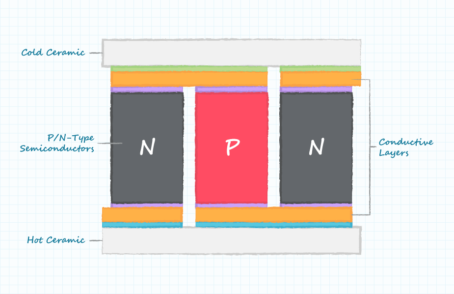
Peltier Module Basics
Peltier modules contain two external ceramic plates separated by semiconductor pellets. One of the plates absorbs heat (becomes cooler) and the other plate dissipates heat (becomes hotter) when a current is passed through the semiconductor pellets. More details regarding the construction and operation of Peltier modules can be found in this technical paper.
The following constraints should be understood when selecting or specifying a Peltier module:
Heat transfer through the module
- Temperature difference across the module
- Temperature of hot side of the module
- Surface area of module
- Required operating current
- Required driving voltage
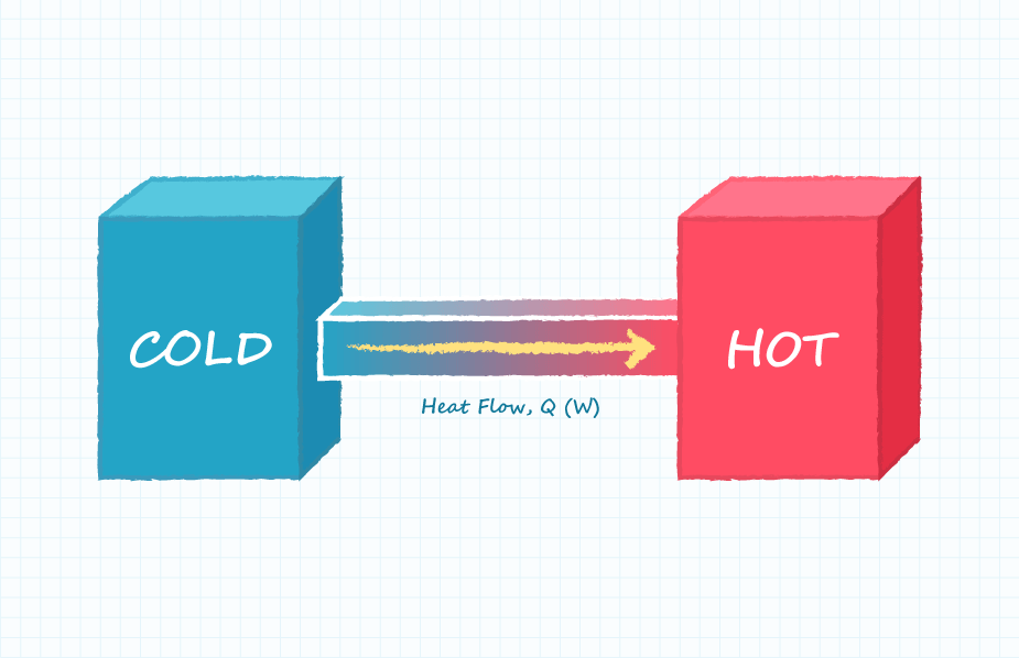
Heat Transfer Through Peltier Modules
The amount of heat to be transferred through a Peltier module from the cold side to the hot side is denoted Q and is specified in Watts. This parameter may be the heat generated by an object to be cooled or it may be the heat conducted to the ambient environment from the object being cooled. It should be understood that Peltier modules do not possess the ability to absorb thermal energy. Peltier modules only transfer thermal energy and the energy being transferred will need to be dissipated on the hot side of the module.
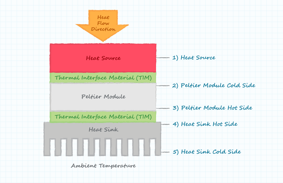
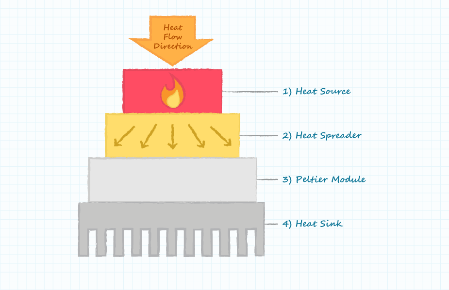
Temperature Difference Across Peltier Modules
The temperature difference specified in a Peltier module datasheet (ΔT) is measured on the outside surfaces of the two ceramic plates of the module. Care must be taken to understand if there is any temperature difference between the Peltier module plates and the external system temperatures of interest. The following diagram indicates five potentially different temperature regions of a Peltier module system.
Temperature of the Hot Side of Peltier Modules
The characteristics of Peltier modules also change with operating temperature. Some vendors, such as CUI, provide specification data for more than one operating temperature. Specification data will probably not be available for the specific operating temperatures of the application and thus the closest available data should be used.
Surface Area of Peltier Modules
The surface area of Peltier modules is typically specified based upon either the area of the object to be cooled or the area available for heat dissipation. An area mismatch between the area available and the area of the Peltier module can be compensated for by the use of a low thermal impedance heat spreader. A simple heat spreader can be manufactured from aluminum or copper.
Required Operating Current
Peltier modules are current-driven devices similar to LEDs. The desired operating parameters are most conveniently achieved by driving the module with a controlled current source and allowing the current source to provide the required load voltage (the voltage compliance of the current source). This is analogous to providing a specific voltage to a voltage driven device and then letting the voltage source provide the required current (i.e. providing a voltage to a microprocessor and ensuring the voltage source can provide the required load current). Peltier modules can be driven with voltage sources but doing so will make it more difficult to accurately control the heat flow and temperature difference across the module.
Required Operating Voltage
The required voltage compliance of the current source will be determined from the Peltier module datasheet and operating constraints.
The Peltier Module I Chose:
I Chose a 40mmx40mm Standard 60w Peltier Module. The Module Peaks at 12v, however i found that it seems to work better at around 8, where 12 just makes both sides hot.
Step 7: Temperature Controlled Chamber


For many drink additives (Juices & Tonic Water), it is imperative that they are kept cool. In order to achieve this, an insulated temperature controlled chamber was designed using peltier technology and temperature sensors.
At a local hardware store i was able to purchase a large sheet of 60mm thick insulation foam. so far this has done a great job keeping the insides of the container cool.
Using a handsaw saw, cut the sheet to the dimensions listed below:
- 426mmx226mm (1x) (base)
- 470mmx426mm (2x) (side wall)
- 470mmx226mm (2x) (side wall)
Using hotglue or super glue, construct the 5 sided container. I recommend building it vertically ontop of the base. Sometimes hotglue guns can melt the stryrofoam, but if you hold the glue about 30cm away from the surface you are applying it too, it has enough time to cool down to the point where it does melt. I found that this worked best, even better than superglue.
Once the foam frame is constructed, Gather the acrylic parts cut on the laser cutter. In case you don't have access to a laser cutter, they have also been designed to be able to be cut on a table saw or with a circular saw. Remember, these parts are not required, but they do make the product feel complete.
- 306mmx106mm (1x) (Cooler Bottom)
- 300mmx467mm (2x) (Cooler Sides)
- 106mmx467mm (2x) (Cooler Sides)
In this case, the smaller walls sandwich the larger ones, with all the walls ontop of the bottom place.
Once the cooler's structure is complete, You will need 3 peltier modules and 3 heat sinks. I was able to find extra heatsinks at an electronics recycling bin. It is important to note that your heat sinks should be able to disperse the energy transferred from the peltier modules. (In my case, the larger one is rated to handle 250w, and the smaller ones 100w. More than enough for the 60w peltier modules)
Using a steaknife, cuttout the foot print of your coolers on one of the larger foam sides. Then using a drill and 40-50mm diameter bit, cut three holes in the acrylic sheet where the heatsinks will go.
On the inside of the cooler, glue a sheet of copper to the wall with the holes in it. I used super glue, but make sure to only glue along the outer edge and away from the holes.
Next, Using thermal paste (Common at any computer store like fryes or radioshack), stick the peltier modules too the copper from the outside. I tend to use an X shape when applying thermal paste, and then let the force of application spread the rest. This seemed to work well.
On the other side of the peltier module, apply more thermal paste, and mount the heat sink to it. If necessary, you may have to drill through the wall and mount the heatsink with nuts and bolts if it is too heavy. Make sure to then attach a fan to the heat sink if it doesn't already have one.
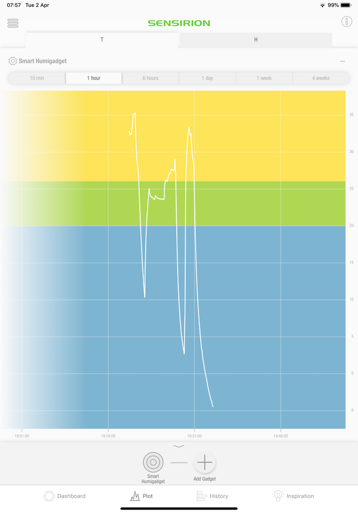
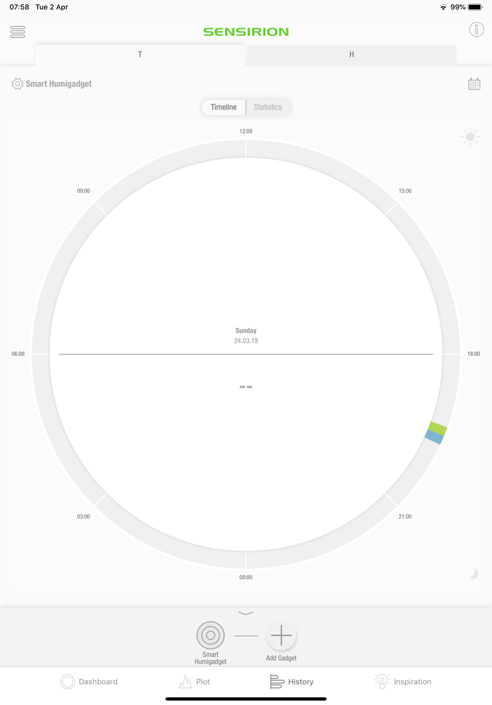
In order to accurately control the temperature of the cooled container, I used a Bluetooth-Temperature Module. The temperature of the container can also be viewed via an app on you android or IOS device. Remotely, you can review the temperature and humidity levels as well as set the desired temp.
Step 8: Lime Slicer
One of the stations on the automated drink maker is an automated Lime dispenser and slicer. A lime drops down a Y-shaped pipe, where it is then forced against a sharp metal grid by a 500N 12v Linear actuator. The grid slices the lime into 4 equal parts, and then drops into the glass. This step is followed by others such muddling and filling the glass with liquid.

In order to mount the linear actuator to the frame and keep all the moving parts stable, I used 32-34mm Pipe claims with Bolt holes on either side. These provided a simple way to mount the actuators and pipes in the upper compartment while keeping everything sturdy. (This actuator provides 500N of force - that"s a lot!)
Step 9: Programming the User Interface (Android Studio)

In order to create a slick user interface to accompany the final product, i decided to use a an android tablet. The tablet has a screen side of 10.1" which makes it perfect for viewing and easily selecting the desired drink. The app's main purpose is to send commands to the arduino over a USB serial connection.
In order to do this, drinks have been put into scrollable horizontal carousels based on their type (Rum, Whisky, Gin.. etc). Each item has an image and name associated with it to make the drink easily identifiable. Once the user clicks on the desired drink, we will make a popup where the user can then change the size (the amount of liquid) they want in addition to inputting personal tweaks (e.g. more ice, more alcohol, more sugar, etc..). Once the drink's characteristics are chosen, the drink can be ordered. A long chain of numbers, each representing a different variable (e.g. quantity of ice), is then generated and sent to the arduino. The arduino interprets this unique drink ID and makes the desired drink as requested.
The Code:
The app consists of three main sections:
- MainActivity.java (this is where all the java and code will go to provide functionality to the app)
- activity_main.xml (This is where the list of drinks are located)
- custompopup.xml (This is the layout page for the custom ordering popup)
Creating the template:
Open up android studio or your IDE of choice and create a new blank app template. This process should automatically create MainActivity.java and activity_main.xml for you. I Also chose to develop my app on android 4.4 (Kit Kat) as this supports almost 90% of devices. Once this is done, we can move on to designing our first page.
Activity_Main.xml:
Activity_main.xml is the primary android layout. For us it will house our list of drinks, an order button, and a custom edit-text forum to insert your own drinkIDs and testing the serial connection.
Start off by creating a linear layout. This will allow us to stack our elements on top of each other for a nice and tidy look.
<linearlayout xmlns:android="http://schemas.android.com/apk/res/android" <br=""><p><LinearLayout</p><p><linearlayout <br="">xmlns:android="http://schemas.android.com/apk/res/android"
xmlns:app="http://schemas.android.com/apk/res-auto"
xmlns:tools="http://schemas.android.com/tools"
android:layout_width="match_parent"
android:layout_height="match_parent"
android:background="@color/colorPrimaryDark"
android:gravity="center|top"
android:orientation="vertical"
tools:context="MainActivity"></linearlayout></p><p><linearlayout <br=""><br></linearlayout></p><p><linearlayout <br=""><br></linearlayout></p></LinearLayout></linearlayout>
Take a look at the steps below and the code that follows for each step.
- Next, we want to add specific elements inside this linear layout. For the custom edit-text bar and controls for the serial connection, create a relative layout and put it inside of the linear layout.
- Now we want to create a carousel for each drink type (Gin, Rum, etc..). This consists of a Text box labeling it, and the carousel itself. I will have three drink types.
- This is what your file should look like
Step 10: Editing MainActivy.java
This one is a little more complicated. Here we will have to make all the functions,classes, and variables that allow the app to run. We will also need to include a method to make a serial connection with the arduino. Yikes!
Please Look at this Gist file for what the entire file should look like or the GitHub Repository for all the files(sorry instructables wouldn't let me embed it.. too big i guess.) I also included all the files in addition to the apk at the end of this step so you can easily install the application on your android deice.
In this step we will create the serial connection that attaches the android app and the arduino together. In addition there will be buttons that will call functions to initiate specific tasks like sending, closing, and opening the connection.
Here we are adding the buttons to force serial-connection related functions.
These variables are the characteristics of any given drink. Changing these will change the drink produced. These are also the values that are sent to the arduino in a string of numbers. (i call that the DrinkID)
Here we are actually creating the carousels and the items within them. Each item has an image associated with it. The name of each drink is already included in the image so it makes it easy to view.
In this section of code we are adding click functionality to each image. When the desired drink is in the center of the carousel, the code is ran for each case.
now we need to create the order button that shows the popup for the final order. here you can select the size of the drink.
here the code creates the DrinkID and order. It then sends this list of numbers to the arduino.
Step 11: Drink Images

For the majority of drink icons and the images used throughout the android application, the came from depositphotos.
The specific icon set i used can be found here: Drink Images For purchase, however i have also included the free versions below (with water marks) if you would like to use those instead. In the files i have included, the images has already been split up into a 3x3 grid to isolate each icon and renamed to make coding easier.
Attachments
Step 12: Programming the Machine (Arduino)
As mentioned above, the arduino interprets the chain of numbers and assigns a variable to each digit. Based on these variables, the drink machine then constructs your drink through a series of steps as shown below.
The arduino file can be downloaded below:
Attachments
Step 13: All the Files
Here are all the files in one place, for easy access so you don't have to scroll through the instructables:
