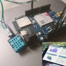
Introduction: Bharat Pi_Sensor_dock
A Bharat pi sensor Dock is an expansion board designed to simplify the process of connecting sensors, actuators, and other peripherals to a Bharat pi Boards. It provides pre-configured pin headers, terminal blocks, and connectors, making it easier to prototype or deploy sensor-based projects.
Supplies
1 Bharat pi Boards
2 Bharat Pi Sensor Dock
3 Sensor
Step 1: How to Connect the Sensor Dock
Step 1: Gather Your Components
Start by collecting the required hardware:
- Bharat Pi Board (referred to as the Base Board).
- Sensor Dock for interfacing with various sensors.
Step 2: Review Pin Configurations
Examine the pin layout of both the Base Board and the Sensor Dock:
- Refer to the datasheets or pinout diagrams for accurate details.
- Identify key pins such as Power (5V/3.3V), Ground (GND), and Communication Lines (e.g., I2C, UART, or SPI).
Step 3: Establish Connections
Carefully align the pins of the Sensor Dock with the corresponding pins on the Base Board:
- Match the power pins to ensure the correct voltage supply.
- Connect communication pins (e.g., SDA/SCL for I2C or TX/RX(GPIO) for UART) appropriately.
Step 2: Connect the PWR SW Pin
Locate the PWR SW pin on the Sensor Dock:
- Use a jumper to connect the PWR SW pin as shown in the power configuration diagram provided with your Sensor Dock.
- This step ensures the proper flow of power between the Base Board and the Sensor Dock
Step 3: Pin Out Diagram
Step 4: How to Connect Sensor
Step 1: Determine Sensor Type
Start by identifying the type of sensor you're working with:
- Analog Sensor: Outputs a variable voltage proportional to the measured parameter.
- Digital Sensor: Outputs discrete signals (high/low) or uses communication protocols like I2C, UART, or SPI.
Refer to the Base Board's pin diagram to check which pins support analog or digital signals.
Step 2: Select the Appropriate Pins
Based on the sensor type:
- For Analog Sensors: Use the analog input pins .
- For Digital Sensors: Use the digital GPIO pins ,designated communication pins for I2C, UART, or SPI.
Refer to the Base Board's pin configuration to ensure proper connections. Check the sensor datasheet for details on required pins (e.g., power, ground, signal).
Step 3: Connect the Sensor
Once you’ve selected the appropriate pins:
- Power Connection: Connect the sensor's power pin to the correct voltage supply (+) .
- Ground Connection: Connect the sensor's ground (-) .
- Signal Connection: Connect the sensor's signal output to the chosen analog or digital input pin on the sensor dock Board.


