

Introduction: DIY Button Plate for Sim Racing Using a Arduino Pro Micro

I will be showing my process of designing and realising a button plate, and teach you a few tricks for designing your own as well. If you want to build the one I'm using as an example, please see 'Supplies' below for the BOM. If you're just following along for inspiration, you can use them as a estimate for your own project.
I've been Sim racing since the summer of 2021. I started with building everything on my own. That includes wheelbase, steering wheel, H shifter, pedals and the rig. I recently bought a steering wheel for cheap on AliExpress, link will be down with the supplies, wanting to build a button box around it and that's what I'm showing today. I will include the files for the pedal shifters, but I won't be explaining them in this Instructables.
The button box will include
- 2x Momentary 3-way toggles
- 6x Push buttons (4 are included with the steering wheel, just need to wire them up)
- 2x Rotary encoders
- 2x Latching 2-way toggles
- LED's
And the tools you'll be needing are
- 3D printer
- Soldering iron
- Laser cutter (Optional for frontplate)
Supplies
STL's: https://www.thingiverse.com/thing:5207013
- 1x Arduino Pro Micro
- 1x male micro USB pinout
Hardware
- 28x M3x4.6x3mm inserts (4x for front plate, 6x for backplate, 8x for mounting the flippers, 10x for mounting the paddles to the backplate)
- 20x M3 washers
- 10x M3x6 (To mount the pedals behind the wheel)
- 10x M3x8 (6 to secure the backplate, 4 for the optional front plate)
- 5x M3x25 (To secure the shifter pedals)
- 3x M5x25 (Shorter bolts to connect the steering wheel to the button plate)
- 3x M5x40 (To connect the whole assembly to your 70mm wheel adapter)
- 1x M4x10 (For the clutch spring)
- 1x M4 washer (For the clutch spring)
- 1x M4 Nut (For the clutch spring)
- 1x Spring, 15mm long, 0.8mm wire thickness, 6mm ID (for clutch spring)
- 3x 7x5mm Aluminium pipe, 24mm long
- Steering wheel: https://nl.aliexpress.com/item/33052964263.html?ga...
Frontplate
- 3mm Plywood 200x160mm
Buttonplate
- Button plate base (250g of filament)
- Button plate backplate (50g of filament)
- 2x Momentary push button (PS102/DS612)
- 2x Latching 2-way toggle (MTS102)
- 2x Momentary 3-way toggle (MTS123)
- 2x Rotary encoder w/ push button (EC11)
- 11x RGB LED (WS2812b 144x/m)
- 1x GX12 female chassis connector
Shifters
- 4x Microswitch (KW11)
- 1x Lineair hall effect sensor (A1302)
- 8x 10x6mm Neo magnets
- 1x 5mm cube Neo magnet
Step 1: Step 1: Looking for a Suitable Steering Wheel and Tracing It's Outlines


First step, though not the hardest, will be our starting point. What kind of steering wheel do you want? Do you want to drive Nascar? Or open-seaters? Maybe just plain old GT cars? Or do you want a more versatile steering wheel?
As I already had a open-seater styled steering wheel, I opted for the GT style of steering wheel. These steering wheels typical have a 360-540degree rotation circle and are around 300mm in diameter. That means a round steering steering wasn't needed. In the end I just chose the cheapest open steering wheel on AliExpress with a size of 310mm.
After receiving your steering wheel, you first need to find out the dimensions of the steering wheel. You can place a piece of paper behind the steering wheel and trace it, make/find a good picture of the steering from the front and trace it using your 3D modelling software or if you're lucky, you can find the CAD model already online.
Make sure to test fit your basic outlines! We don't want to print out the whole thing and find out the buttons are too low. See the example picture, with the blue test piece, I could see the alignment of the 70mm bolt pattern, the 4x included buttons and the outlines.
Pictures: AliExpress
Step 2: Step 2: Deciding What Kind of Functions You'd Want and an Introduction to SimHub Arduino Tool


An Arduino Pro Micro has 18 IN/OUT pins. Let's see how we can utilise these:
- Rotary encoders need 2 pins each
- Latching toggles don't work in button matrices, so these will need to be wired independently
- LED's only need 1 pin, no matter the length
- Potentiometers and hall effect sensors also need a pin for itself
- Screens, if you want to add them yourself, need 2 pins
I went for
- 2x rotaries
- 2x 3-way toggles
- 6x push buttons
- 4x on/off pedals
- 1x analog pedal
- 2x latching toggles
- LED's
This means I'll need 4 pins for the rotaries, 2 pins for the latching toggles, 1 pin for the LED's, 1 pin for the analog input and 8 pins for a 4x4 button matrix. I'm now left with 2 pins for future use, maybe a screen?
SIMHUB
A very nice tool to use for this is SimHub. SimHub offers a Arduino tool to create your own button box/plate. Choose your Arduino type and add your functions as you please. Some options are throttle input, individual buttons, button matrices, rotary encoders, PWM outputs.
On the right side of the tool you see how populated your Arduino is, and how much space you have left.
Pictures: Simhub
Step 3: Step 3: Electronics, It's Enclosure and Wiring


The placement of your electronics will be very important for your racing experience later on. Having buttons identifiable by feel will be a god-send when you are busy going 3-wide through T1. Ways to make buttons easily identifiable are:
- Using different size button caps
- Using ridges to differentiate
- Spacing, so i.e. 1 button in the top left of the steering wheel, 1 in the middle and 1 in the button
- Try avoiding using other buttons as a feeler to prevent mis-clicks.
I only have 3 buttons per side, so I decided that spacing would be sufficient.
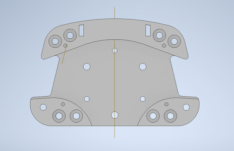
Start with a basic plate, for 3D printing 3mm would have been enough, but I chose 4mm to match the thickness the of the steering wheel itself. The internal height of the box should be at least the height you need to mount your electronics, for me that was 16mm. Raise your sides to match this height, plus 2mm for ease of soldering and 3mm of whatever the thickness of your backplate is.
Remember, when designing your own base, to leave space for cables, nuts for plate mounted components and your fingers and screwdrivers during installing. It's better to have too much space than too little.
The backplate will house the base for the shifter and clutch pedals. Make sure your pedal shifters don't block any shaft adapter.
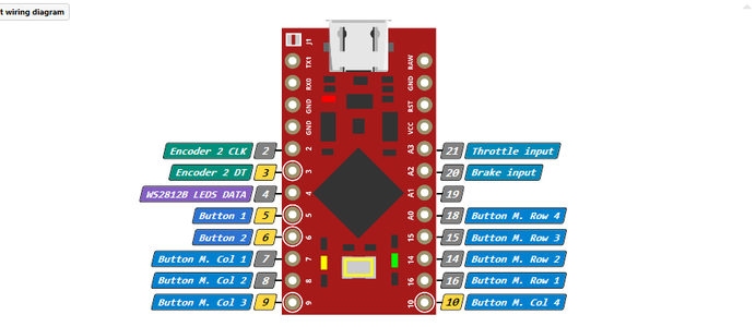
Wiring the button plate will be the most tedious task of this tutorial. Follow the wiring diagram found in this step. Watch out how you wire those 3-way toggles in the button matrix.
A tip for wiring button matrices, assign a number/name to each button and make table for yourself, use different colour wiring for rows/columns, see picture for example: I'll use red for the rows, and black for the columns.
Use a 'micro USB male pinout connector' (IDK how you call this, see picture) and don't solder on to the existing usb port.
STL's: https://www.thingiverse.com/thing:5207013
Pictures: Simhub, Aliexpress
Step 4: Step 4: the Arduino Code

Let me start by saying this: you don't need to write a single line yourself.
That's the beauty of SimHub. It's as easy as selecting your functions on the left side of the tool and assign the pins accordingly. Note: Simhub doens't show the 0/1 pins on the Pro Micro, but you can still assign them. Don't forget to enable game controller on the top and give it a name. As you can see I could mine 'GT rim 310mm'.
When selecting port, it's usually a smart idea to unplug any other microcontrollers, so you won't upload the sketch to the wrong board by accident. And press 'Upload to Arduino', easy as that. SimHub will include the libraries they need.
Pictures: Simhub
Step 5: Step 5: Frontplate (Optional)

To cover up the 3D printed front face, you could chose wraps, or sand it down and paint it. I went for the easy right and used a laser cutter and 3mm plywood. I could've gone with 3D printing, but the accuracy and simplicity of using laser cutters made it very hard to choose something else. I wanted to etch the basic functions onto it, like Traction Control up or down, but didn't in the end, because I don't want to limit myself.
As for the LED's, you can leave them uncovered. I don't recommend it though. The LED's are quite sharp for your eyes with a diffuser. This is easy to fix by printing a thin piece of white cover for them. Or you could go fancy and used 'smoked acrylic'. I went for the first method, but add walls to slightly separate the LED's, wont do much though cuz it's 0.8mm thick white plastic.
