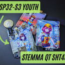
Introduction: ESP32-S3 YOUTH #2 - How to Run RGB & Buzzer?
Hello fellas!
In this article, I’ll explain how to properly work with the RGB LED and buzzer located on the board. You'll learn how to connect them in the Arduino IDE and integrate them into your future projects.
Before we dive in, make sure you’ve read the article where I cover the board and its setup in detail—it’ll make everything much easier to follow.
Technical Overview:
The board features an electromagnetic buzzer FUET-5030 (3.3V logic), which not only supports simple on/off operations but can also produce different tones. This makes it perfect for playing melodies and adding some audio flair to your projects.
Additionally, there’s an RGB LED XL-5050RGBC-WS2812B-S (5V logic, controlled via a 3.3V transistor). This LED is easily managed using the NeoPixel library, which simplifies control. The board is designed to support both the onboard LED and external WS2812B LED strips, as long as their power supply matches the required 5V. This means you can light up a single LED or go all out with a full LED strip for your colorful creations.
Let’s get started with some code examples to bring these components to life!
Supplies
You can find any of these boards on my Tindie store:
Step 1: RGB LED Usage
Each RGB LED consists of three interconnected diodes—red, green, and blue.
By adjusting the intensity of each diode, you can create any color you want. The brightness of each diode is controlled by a signal ranging from 0 to 255—the higher the number, the brighter the light. Now, let’s move on to practice!
Getting Started:
- First, we’ll need to download the Adafruit NeoPixel library—it makes working with RGB LEDs a breeze. (See screenshots 1 and 2.)
- After downloading the library, create a folder on your PC (I recommend Documents > Arduino) and name it ESP32_Youth_RGB.
- Download the attached file ESP32_Youth_RGB.ino and place it in the folder you just created. Open the file in Arduino IDE and upload it to the board.
Watch the Light:
Once the upload is complete, press the "Rst" button on the board and enjoy the light show!
P.S. Before connecting the board, make sure the switch on the left side is in the "ON" position. Otherwise, the show’s not starting.
P.S.S. After uploading the new code, the signal remains on the transistor's gate and doesn’t turn off automatically. To turn it off, you’ll need to unplug the USB.
Attachments
Step 2: Buzzer Test
Now let’s move on to the buzzer! For this part, we’ll need two files: one contains the main code for controlling the buzzer, and the other includes the necessary notes and frequencies to play various sounds.
Steps to Get Started:
- Create a new folder named ESP32_Youth_Buzzer in the same repository from step 1 (Documents > Arduino).
- Download the attached files ESP32_Youth_Buzzer.ino and pitches.h, and place them in the folder you just created.
- Open the file Buzzer.ino in Arduino IDE and upload it to the board.
Let the Sound Begin:
Once the upload is complete, press the "Rst" button on the board and listen to the results. 🎵
Enjoy experimenting with different tunes and sound effects!
Step 3: Do They Work Together?
Now let’s level up and run both programs at the same time. This time, we’ll combine the RGB LED effects with the buzzer to create something even more interesting.
How to do it:
- Create a new folder named ESP32_Youth_Mario_RGB in the repository from step 2 (Documents > Arduino).
- Download the attached files ESP32_Youth_Mario_RGB.ino and pitches.h, and place them in the folder you just created.
- Open the file ESP32_Youth_Mario_RGB.ino in Arduino IDE, upload it to the board, and hit "Rst".
Now you know how to combine sounds with lights and you are ready to increase yor future projects quality by adding thin knowledge into them!
Step 4: In Conclusion
Thank you for reading this article! If you have any questions or if something doesn’t work, feel free to ask in the comments section.
By the way - don't forget to check all Collection in my Tindie shop :)


