

Introduction: Fun Led and Buzzer Timer Arduino Circuit


This instructable consists of a step-by-step process to help create a Led and buzzer Timer. In this circuit, once the pushbutton is pressed every 2 seconds another LED will light up as it counts to 10 seconds. Once the 10-second timer is over the piezo buzzer will beep for 3 seconds while the LED's all-flash to let you know your timer is done.
Here are some similar circuits with similar codes:
- https://www.electronics-tutorials.ws/blog/7-segmen...
- https://create.arduino.cc/projecthub/ianabcumming/...
- https://create.arduino.cc/projecthub/tylerpeppy/ar...
- https://create.arduino.cc/projecthub/dmytrosavchuk...
The circuits above have similar coding as the one done in this circuit, these codes used the general structure used in almost every Arduino code, starting off with the variables, the void setup (whether the component is OUTPUT or INPUT), and lastly, void loop(functions to be carried out in this code). As learned in previous lessons specifically the 7 segment display in class this Arduino circuit uses the "delay" function which pauses the program for the amount of time (in milliseconds) specified in the parameter, the "for" function used to repeat a block of statements enclosed in curly brackets, alongside the "digital write" function was also used in this circuits code to write a HIGH or a LOW value to a digital pin, such functions were learned throughout the TEJ course and helped develop a successful circuit code utilized in this project.
Step 1: Supplies


- Arduino Board (https://www.amazon.ca/ATmega32U4-16MHz-Leonardo-Mo... )
- Male to female jumper wires (2) (https://www.amazon.ca/Elegoo-120pcs-Multicolored-B...)
- Buzzer(1) (https://www.amazon.ca/Cylewet-Electronic-Magnetic-...)
- Red led (2) ( https://www.amazon.ca/Projects-B-0001-B07-Red-LED-...)
- Green led(2) (https://www.amazon.ca/Projects-B-0001-A01-Diffused...)
- Yellow led(1) (https://www.amazon.ca/Diffused-Lighting-Emitting-R...)
- 560-ohm Resistors (5) (https://www.amazon.ca/EDGELEC-560-ohm-%C2%B11-Resi...)
- Pushbutton (1) (https://www.amazon.ca/C-J-SHOP-Miniature-Momentary...)
- Breadboard (1 )(https://www.amazon.ca/Breadboard-Solderless-Protot...)
- Cable (https://www.amazon.ca/DTECH-Printer-Cable-Feet-Spe...)
- 10 k ohm resistor (1)(https://www.amazon.ca/Projects-10EP51210K0-10k-Res...)
The links to buy each component is also provided in case some components are missing. Once all your components are gathered move onto Step 2...
Step 2: Assemble Your Circuit


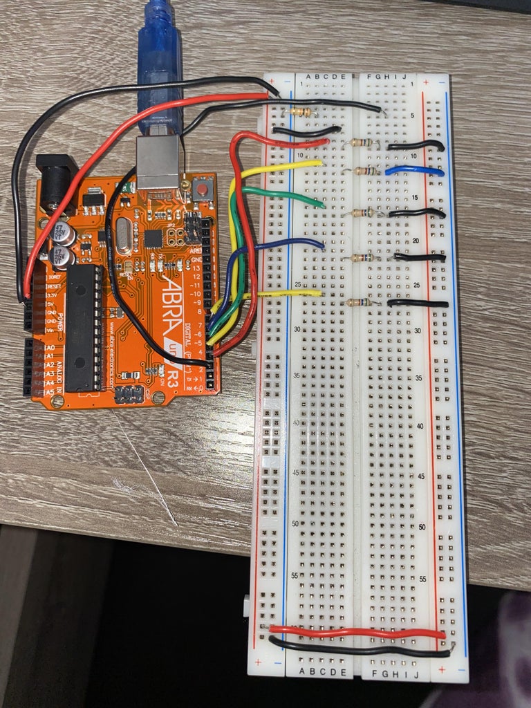

With the help of the schematic above build your circuit in real life with all the required components, for additional help here's the link to the public tinkercad circuit :
https://www.tinkercad.com/things/1DU3sCunuE2-final...
- Start off by completing the wiring on the breadboard to help avoid wrong wiring
- Next, insert the five 560 ohm resistors in the middle of the breadboard (ensure to follow the wiring and location of each component according to the ones in tinkercad to prevent the circuit from not working)
- Following the resistors insert your pushbutton near the top of the breadboard above the resistors in the same pin located as the one in tinkercad
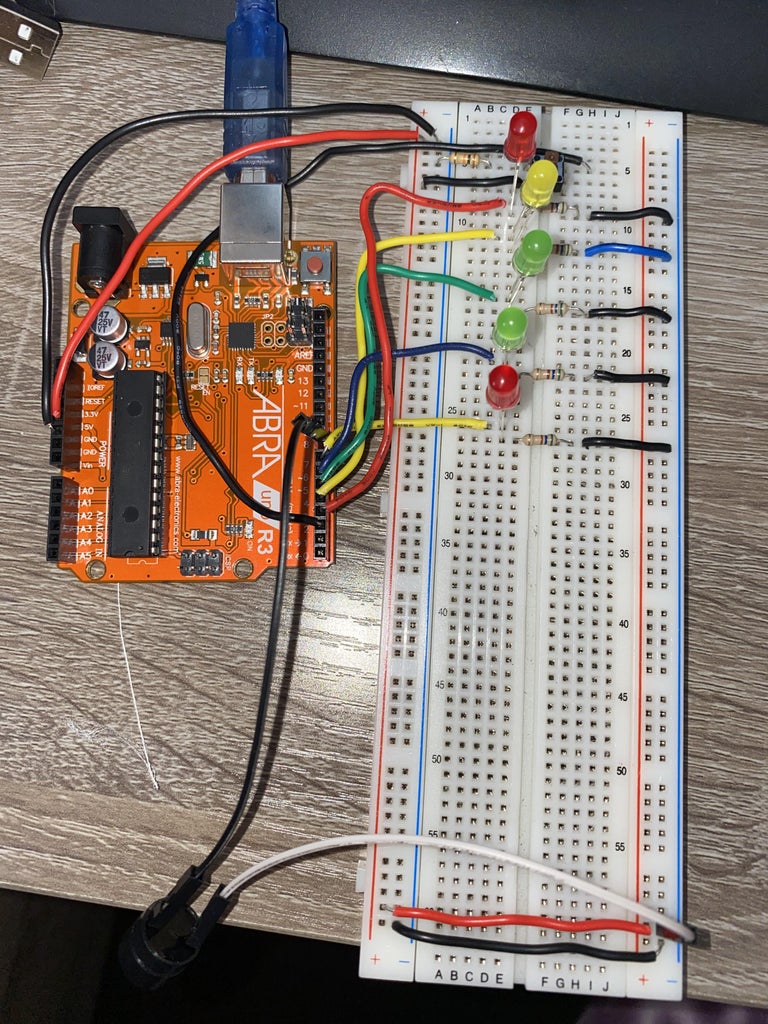
- Add each led in the order of red, yellow, green, green, and red (colors of the led can be changed according to your choice however change the name of each component in the code to avoid confusion)
- With the wiring and most of the components done follow up with the buzzer that will be responsible for making the timer go off, with the help of the two male to female jumper wires attach the buzzer and locate one side of the wire in the Arduino pin 8 and the second jumper wire will be attached to the breadboard (Look at the tinkercad for a clearer idea of the location of the pin).
- Finally, with the wiring is done and all the components attached make sure to review the wiring and ensure its the same as the one in the tinkercad to avoid troubleshoot and the circuit failing, unless you would like changes of your own which would also require you to change the code accordingly.
Step 3: Coding

[ The link below leads to the Arduino file for the code ]
As mentioned before this circuit is coded to create a simple timer that starts by pressing one pushbutton and leads to 5 LEDs going off alongside a buzzer each at its allocated time. With the components attached to the breadboard and the wiring done you can now insert the code to make the circuit work.
The following also is a copy of the code in case the arduino file is not accesible:
int Red = 3; // The Red LED Pin
int Yellow = 4; // The Yellow LED Pin
int Green = 5; // The Green LED Pin
int greentwo = 6; // The Blue LED Pin
int redtwo = 7; // The White LED Pin
int Push = 2; // The Push Button Pin
int Buzzer = 8; //The Buzzer Pin
int Value = 0; // A changable value
int Repeat = 0; // A changable value
int Value2 = 0; // A changable value
int count; // Used in the "for" statement int max; // Used in the "for" statement
void setup() { Serial.begin(9600); pinMode(Red, OUTPUT); // Initialize pin mode pinMode(Yellow, OUTPUT); // Initialize pin mode pinMode(Green, OUTPUT); // Initialize pin mode pinMode(greentwo, OUTPUT); // Initialize pin mode pinMode(redtwo, OUTPUT); // Initialize pin mode pinMode(Push, INPUT); // Initialize pin mode pinMode(Buzzer,OUTPUT); // Initialize pin mode }
void loop() { Value = digitalRead(Push); // Read push button state and assign its value to "Value" Serial.println(Value); if (Value == HIGH) { // If push button is pressed start this string Repeat = 1; // Set "Repeat" value to 1 to start the next string even if push button is released } if (Repeat == 1) { // When "Repeat" equals 1 start this sring delay(2000); // Wait for 2000 millisecond(s) digitalWrite(3, HIGH); // Turn on Red LED delay(2000); // Wait for 2000 millisecond(s) digitalWrite(4, HIGH); // Turn on Yellow LED delay(2000); // Wait for 2000 millisecond(s) digitalWrite(5, HIGH); // Turn on Green LED delay(2000); // Wait for 2000 millisecond(s) digitalWrite(6, HIGH); // Turn on second green LED delay(2000); // Wait for 2000 millisecond(s) digitalWrite(7, HIGH); // Turn on second red LED for (count=0;count<5;count++) //Starts the next string and repeats it 5 times { digitalWrite(Buzzer, HIGH); // Turn on the Buzzer delay(500); // Wait for 500ms digitalWrite(Buzzer, LOW); // Turn off the Buzzer delay(500); // Wait for 500ms digitalWrite(3, HIGH); // Turn on Red LED digitalWrite(4, HIGH); // Turn on Yellow LED digitalWrite(5, HIGH); // Turn on Green LED digitalWrite(6, HIGH); // Turn on second green LED digitalWrite(7, HIGH); // Turn on second red LED digitalWrite(Buzzer, HIGH); // Turn on the Buzzer delay(500); // Wait for 500ms digitalWrite(Buzzer, LOW); // Turn off the Buzzer delay(500); // Wait for 500ms digitalWrite(3, LOW); // Turn off Red LED digitalWrite(4, LOW); // Turn off Yellow LED digitalWrite(5, LOW); // Turn off Green LED digitalWrite(6, LOW); // Turn off second green LED digitalWrite(7, LOW); // Turn off second red LED delay(500);// Wait for 500ms }} Repeat = 0; // Changes "Repeat" value to 0 until the push button is pressed again }

Step 4: Finished!
The link below shows a video of what your circuit should look like after following all the steps:
To start the circuit press the push button and the timer will go off, you can adjust the timings in between each pause through the code, additionally, you can change the led colors to your liking. This is an easy and fun project to try at home and even further modify.
