Introduction: Giant Dial Lamp

This is a 3D printed LED lamp project that looks like a giant dial. Turn it, and watch it glow from the inside.
This instructable is a companion to the webinar series I hosted in March of 2017. Design Now: Hour of Making in Motion focused on mechanical assemblies and integrating electronic parts in Fusion 360. You can watch the full webinar video here:
And check out the other two webinars in the series here: Hour of Making in Motion: Design a Fidget Spinner, and Hour of Making in Motion Lesson 3: Perpetual Clock with Arduino
Step 1: Tools and Materials
All the parts can be purchased on Amazon. You can also buy the hardware on McMaster-Carr, which may be more convenient because you can make an order through Fusion.
ELECTRONICS
- 12V DC Terminal: $5.39 on Amazon
- DC Terminal: $2.45 for 5 on Amazon
- Warm White 12V LED Strip: $8.18 on Amazon
- 12V LED Dimmer: $11.96 on Amazon
- 20 GA Wire: $5.46 on Amazon
- Heat Shrink Tubing: $6.75 on Amazon
HARDWARE
- Machine Screw: M2 X 8mm Flat Head: $6.45 for 25 on McMaster-Carr
- Machine Screw: M4 X 8mm Rounded Head: $9.47 for 100 on McMaster-Carr
FILAMENT
Any filament will do, but I like the results I get with Alchement Wood Fiber PLA. It's out of stock on Amazon, but I think this one will have pretty much the same look:
- Hatchbox 3D Wood PLA 1.75mm: $34.99 on Amazon
TOOLS
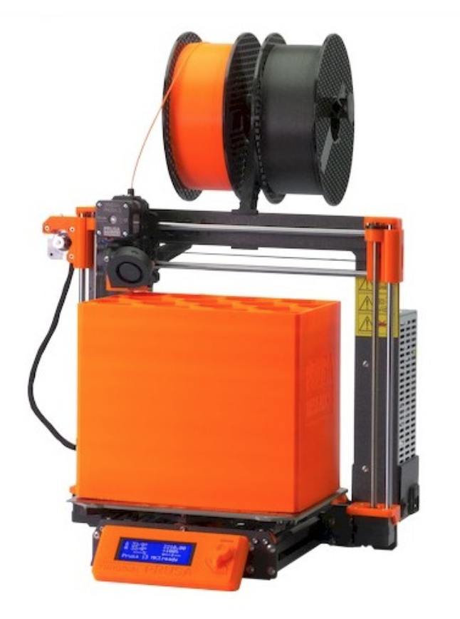
I use a Prusa I3Mk3S for just about everything. It's the best bang for your buck, in my opinion- very well made, 3D printable replacement parts, accurate and reliable.

- Soldering Iron: $17.99 on Amazon.
Step 2: 3D Modeling + Printing
Above is a screencast of me rebuilding the model based on the original one I had designed previously. If you click on the actions in the different tracks, you can follow my work flow.
Fusion 360 is free for students and hobbyists, and there's a ton of educational support on it. If you want to learn to 3D model the kind of work I do, I think this is the best choice on the market. Click the links below to sign up:
This project is the subject of a webinar I'll be hosting on March 29th as part of a series called Design Now: Hour of Making in Motion. I'll be covering mechanical assemblies, integrating electronic parts, and general modeling techniques.
The files attached in this step are as follows:
- The F3D is the complete design in a Fusion 360 archive format. If you're new to Fusion, please sign up for my free 3D Printing class. In Lesson 2 you'll find instructions on how to get a free license as a hobbyist or student / educator.
- The STLs are printable files that you can bring into any slicer
The design is pretty simple, it's a base with a dimmer built in, and a cap that acts as a giant knob. There's a ring on the inside that keep the knob cap in place, and the knob cap plugs into the potentiometer post on the dimmer. With the base stationary, twisting the knob cap turns the potentiometer and dims the LEDs.

Step 3: Assembly

The assembly is really simple. All the holes are sized properly in the model, so the whole thing just snaps together.

All the parts you need are seen above.

1. The LED strip has adhesive backing. Cut the strip to size so that it fist on the rim, then remove the backing and stick it to the base. You may also want some extra glue or a hot glue gun for the LED strip.


2. Insert the DC terminal and fasten it in place with the provided nut and washer.

3. Solder the wires to the leads on the LED strip and to the DC terminal. Give yourself enough length to work with in case you need to make corrections. Generally Red is + and Black is -, but it doesn't really matter because you've only got two options and you can switch the wires on the screw terminals if the LEDs don't come on.

4. Push the dimmer into the hole in the bottom of the base, then use the M4 screws to fasten it in place.


5. The wiring is dead simple. Just insert the stripped ends into the appropriate screw terminals. IN is where you screw in the wires from the DC terminal, and OUT is for the wires from the LED strip. When you plug in the 12V adaptor, the lamp should now turn on automatically.
In this picture you can see I've also put the ring on.


6. Now that the base and electronics are assembled, it's time to add the knob cap. There are two semicircular holes that match the dimensions of the top of the potentiometer. Just line up the holes and press down.
In retrospect, it might have been better to just have a single hole. The metal post of the potentiometer is made so that you can widen the gap with a flat head screwdriver. This would have made it easier to press on and would have made it adjustable.
7. Now that everything's in place, just line up the ring holes with the tapped holes in the underside of the knob cap and screw in the M2 screws.
Step 4: Lessons Learned
Overall this project was pretty successful and worked on the first try. If I were to do it over, I would probably pay more attention to the location and exposure of the LED strip. I recessed the LEDs up into the knob shell in order to hide them, but it doesn't emit much light as a result. I think having some exposure would be an acceptable trade off for more light. After all, it's hanging on a wall, so you wouldn't really see the LEDs anyway.


