Introduction: How to Design a Lock Using SelfCAD


Learn How to Design a Lock Using SelfCAD with the help of this article
Step 1:
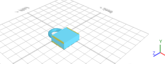
How to Design a Lock Using SelfCAD
The art of lock design has evolved significantly over the centuries, from simple mechanical devices to complex digital security systems. However, the fundamental principles of creating a secure, functional lock remain rooted in precision, creativity, and an understanding of mechanical principles. In modern design, 3D modeling software has revolutionized the way locks can be conceptualized and created. SelfCAD, a versatile and user-friendly 3D modeling tool, offers an excellent platform for designing locks, even for beginners. This article explores the process of designing a lock using SelfCAD, highlighting the essential steps from initial modeling to final touches, and demonstrating how the software's features can simplify and enhance the creation of secure and aesthetically pleasing lock designs
To access the interactive tutorial to this article, check out https://www.selfcad.com/tutorials/163o6v582n1r246x16363jz293o71l4z1e1q
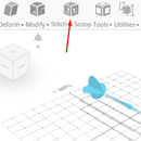
Once you’ve launched the editor;
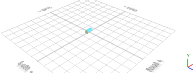
From the 3D Shapes category on the toolbar choose Cylinder; Set top radius to 10, bottom radius to 10, height to 40, vertical segments to 32, rotation z to 90
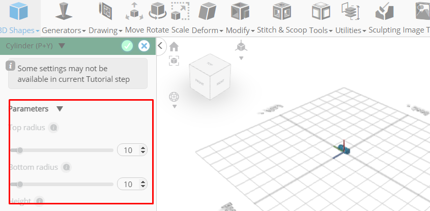
Click to finalize cylinder
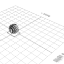
Click to activate polygon selection; Click on highlighted region to select it
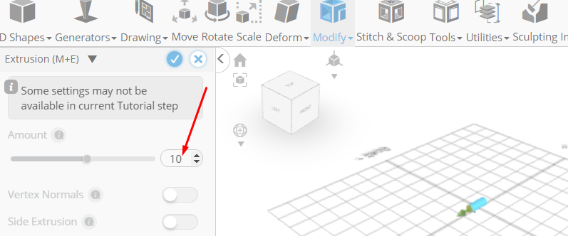
From the modify category on the toolbar choose extrusion; Set extrusion amount to 10
Click add option to add next macro step;Set operation to rotate, Set y to -15, Set amount of copies to 12
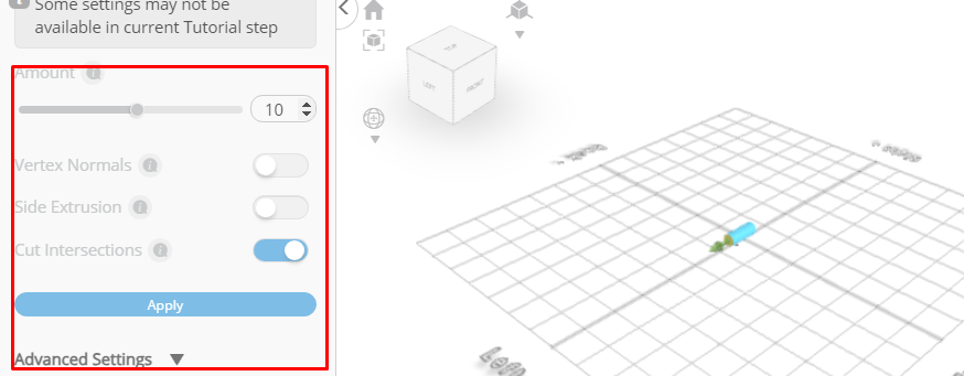
Click to finalize extrusion
From the modify category on the toolbar choose extrusion; Set extrusion amount to 50
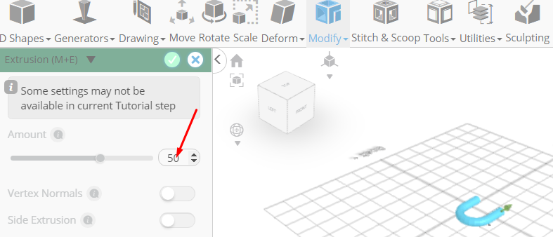
Click to finalize extrusion
From the 3D Shapes category on the toolbar choose Cube; Set height to 40, depth to 120, position x to 50, position z to 40
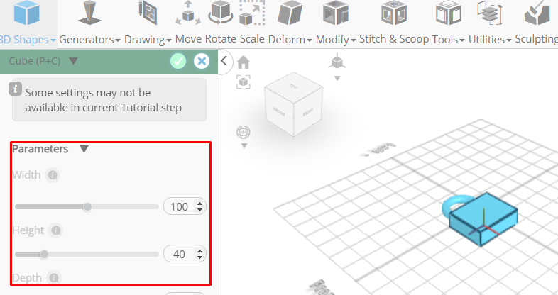
Click to finalize cube
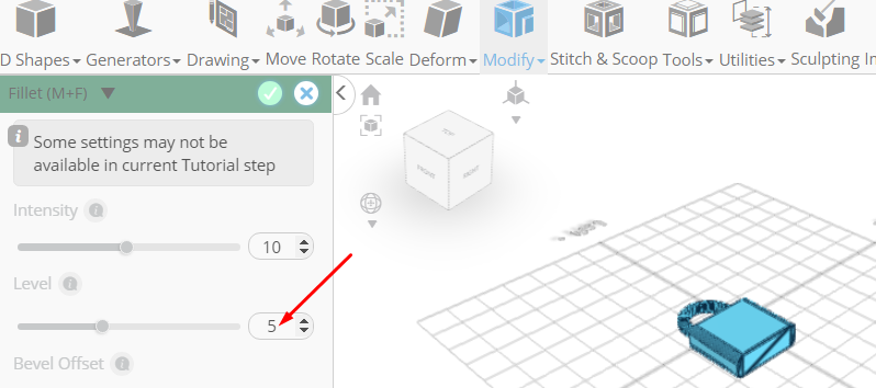
Click to activate edge selection; Click on highlighted region to select it
From the modify category on the toolbar choose fillet; Set level to 5
Click highlighted part on selection cube to turn off region selection
Click on mesh 4 to select it. Click on mesh 8 to deselect it
Click move on the toolbar; Set y to 10, Set z to 38.98
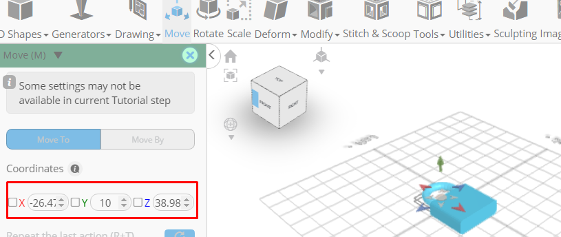
Click ‘x’ to close transformation panel
From the 3D Shapes category on the toolbar choose Cylinder; Set top radius to 20, bottom radius to 20, height to 30, vertical segments to 32, position x to 75, position y to 12, position z to 39
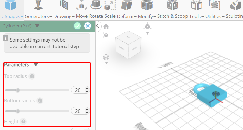
Click to finalize cylinder
Click on mesh 8, 4 to select
Click stitch & scoop on the toolbar; From the tool panel choose difference, Choose mesh 4, mesh 12 to subtract and set keep subtracted object to true
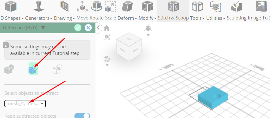
Click to finalize difference
From the 3D Shapes category on the toolbar choose Cube; Set width to 20, height to 10, depth to 5, position x to 75, position y to 32, position z to 39
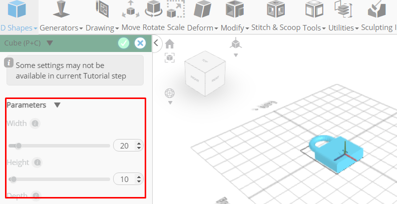
Click to finalize cube
Click on mesh 12 to select it
Click stitch & scoop on the toolbar; From the tool panel choose difference, Choose mesh 16 to subtract
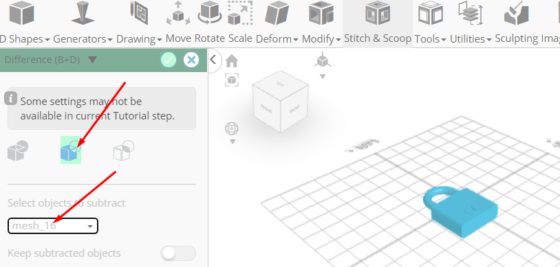
Click to finalize difference
As you continue honing your design skills, remember that SelfCAD offers a wealth of resources to support your learning journey. To deepen your understanding and explore more advanced features, consider checking out the interactive tutorials (https://www.selfcad.com/tutorials) available on the SelfCAD website. The tutorials page provides a treasure trove of guides, tips, and tricks that cater to designers of all levels.
More structured learning experience can also be accessed at the SelfCAD Academy (https://www.selfcad.com/academy/curriculum/), https://www.youtube.com/@3dmodeling101, and 3D Modeling 101 series (https://www.youtube.com/playlist?list=PL74nFNT8yS9DcE1UlUUdiR1wFGv9DDfTB). This comprehensive resource offers in-depth courses taught by industry experts, allowing you to master the intricacies of SelfCAD at your own pace.