Introduction: INTERACTIVE INTERNET CLOCK
Today, I would like to share how to make an internet clock with interaction effect by P2.5 RGB LED MATRIX 64x64. This clock not only displays the time but also interacts with our motion. It simulates the LEDs as particles of sand and when we interact with clock matrix, particles of sand will move as if they were affected by gravity. Time and motion data are collected and controlled by a MPU6050 (Accelerometer + Gyro) and NODEMCU-32S.
Let's get started.
Step 1: PARTS LIST
Main parts are listed as below:
- 1pcs x P2.5 64x64 RGB LED Matrix.
- 1pcs x NodeMCU-32S ESP32 Microcontroller module.
- 1pcs x MPU6050 Accelerometer + Gyro.
- 1pcs x Double Side Prototype PCB Circuit Board 9x15cm
- 2pcs x Female 40pin 2.54mm Header.
- 1pcs x 40Pin 2.54mm Single Row Round Female Pin Header.
- 1pcs x Power Supply Socket Jack Plug Connector Cable.
- 1 meter x Rainbow Color Flat Ribbon Cable.
- 1pcs x White Acrylic Plate A4 size.
- 1pcs x Power Supply 5V minimun 2A.
Step 2: WIRING DIAGRAM
Input Connector (PI) and Output Connector (PO) of P2.5 RGB LED Matrix 64x64 is labeled in the above picture.
And the wiring diagram between ESP32 (NODEMCU-32S), P2.5 LED MATRIX 64x64 and MPU6050 are shown in the table below.

Step 3: SOLDERING WORKS
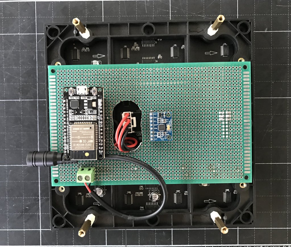
This P2.5 RGB led matrix 64x64 has a dimension Width x Length = 16 x 16cm. All the components, wires can be soldered on a double-side copper prototype PCB 9x15cm. With my instructable, after finishing soldering, we can plug this PCB into PI and PO of P2.5 RGB LED MATRIX 64x64, like a Shield. In the future, it have enough space to add some extra components on this PCB board.
- Marking and drilling a hole on the Double Side Prototype PCB at the power supply position of the RGB LED Matrix

- Soldering female header at PCB bottom for connecting from ESP32 to Input Connector (PI) and Output Connector (PO) of RGB LED Matrix 64x64. Tip: In order for all wires can go through easily under PCB, I have stacked 8 pin "RECTANGULAR FEMALE HEADER" on the 8 pin "ROUND FEMALE HEADER". After soldering, we can use super glue to attach them tightly together.


- Soldering female headers at PCB top for NODEMCU-32S and MPU6050, then soldering the circuit following the previous step
*** TOP view of PCB after soldering

*** BOTTOM view of PCB after soldering

- Plug NODEMCU-32S and MPU6050 on the PCB

- Plug PCB female headers to Input Connector (PI) and Output Connector (PO) of RGB LED Matrix 64x64, then plug 4 wires power supply from PCB to led matrix.

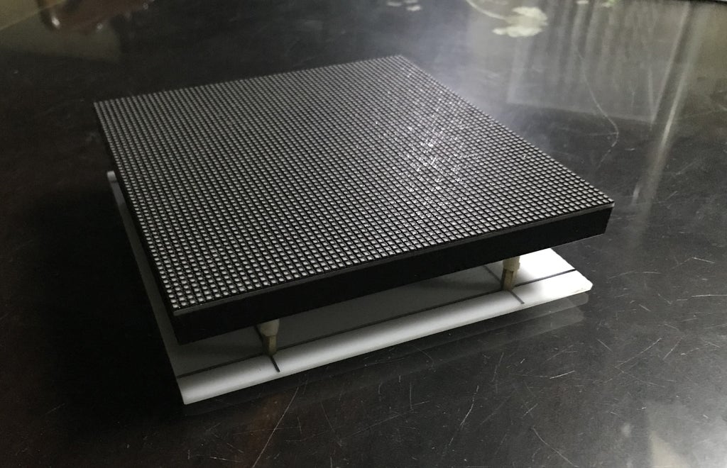
- Cover the back side of RGB LED Matrix by White Acrylic Plate

- Done


Step 4: PROGRAMING
My program is referenced to the following sources:
- https://learn.adafruit.com/matrix-led-sand
- https://github.com/witnessmenow/Falling-Sand-Matri...
- https://github.com/adafruit/Adafruit_PixelDust
- https://github.com/porrey/ledmatrixide
Libraries are used in my program:
- PxMatrix library: https://github.com/2dom/PxMatrix
- MPU6050 library: https://github.com/witnessmenow/Arduino-MPU6050
- Adafruit GFX library: https://github.com/adafruit/Adafruit-GFX-Library
- NTPClient library: https://github.com/arduino-libraries/NTPClient
You can download full code of interactive internet clock at my GitHub.
NOTES:
- MPU6050 connect to ESP32 NODEMCU-32S by following pins:
*** SDA (MPU6050) - GPIO27 (NODEMCU-32S)
*** SCL (MPU6050) - GPIO26 (NODEMCU-32S)
mpu.begin(MPU6050_SCALE_2000DPS, MPU6050_RANGE_4G, MPU6050_ADDRESS, 27, 26))
// SDA - GPIO27 and SCL - GPIO26
- As mentioned from Dominic Buchstaller (PxMatrix's author), some panels have a slow multiplexer and only a partial image is displayed. To remedy this we can add some delay to the multiplexing function to set the time in microseconds that we pause after selecting each mux channel
setMuxDelay(uint8_t mux_delay_A, uint8_t mux_delay_B, uint8_t mux_delay_C, uint8_t mux_delay_D, uint8_t mux_delay_E);
My Chinese friend bought for me this P2.5 RGB LED MATRIX with a very cheap price from Taobao (about RMB66.5). After applying this function, it worked perfectly otherwise my led matrix can't show anything.
display.setMuxDelay(0,1,0,0,0);

- You can adjust the time offset to your timezone
#define NTP_OFFSET 25200 // This is Vietnamese Time Zone
- You can change the font for numbers and strings
#include <Fonts/FreeSansBold9pt7b.h>
#include <Fonts/FreeSansBold12pt7b.h>
#include <Fonts/FreeSansBold18pt7b.h>
#include <Fonts/FreeMonoBold24pt7b.h>
- The "CLOCK" in the middle of led matrix is defined as an obstacle
imgWrapper.setCursor(0, 26);
imgWrapper.setFont(&FreeSansBold9pt7b);
imgWrapper.setTextColor(myWHITE);
imgWrapper.print("CLOCK");
And this obstacle "CLOCK" is displayed on the led matrix as following codes below and we can change it by replacing the "CLOCK" string to other strings or images.
display.setCursor(0, 32);
display.setFont(&FreeSansBold9pt7b);
display.setTextColor(myWHITE);
display.print("CLOCK");- In order clock matrix can interact exactly with motion, we should double-check actual position of MPU6050 on the PCB to see how it correlates with coordinates of the matrix led. Base on this, we can adjust the programing code accordingly.
Step 5: SOME TESTINGS
On instructables website and GitHub, we have lots of amazing led projects and I have tested them on my 64x64 led matrix, such as:
- GRAVITY EFFECT by Brian Lough and Daniel Porrey.
- TETRIS CLOCK by Brian Lough and MORPHING DIGITAL CLOCK by HariFun.
- We can add some more components on 9x15cm PCB, specifically, I soldered 2 x MSGEQ7 for adding 2 channels spectrum analyzer function to the led matrix board. It's great, I can play on this led matrix in my free time.

Step 6: FINISH
Thank for your watching!
Please LIKE and SUBSCRIBE to my YouTube channel.


