Introduction: Interfacing RF Transmitter and Receiver Module With Arduino
In this project, we will employ RF Transmitter and Receiver Module with Arduino Uno to send the data from RF transmitter to RF Receiver.
Step 1: About RF Module(FS1000A 433mHz):
This RF module comprises of an RF Transmitter and an RF Receiver. The transmitter/receiver (Tx/Rx) pair operates at a frequency of 433 MHz. An RF transmitter receives serial data and transmits it wirelessly through RF through its antenna connected at pin4. The transmission occurs at the rate of 1Kbps – 10Kbps. The transmitted data is received by an RF receiver operating at the same frequency as that of the transmitter.
Step 2: Components Required:
- Arduino board with cable 2
- RF Module 1
- Jumper wires
- Breadboard 1
- LED 1
You can buy these components from elegocart.
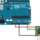
Step 3: Transmitter Setup:
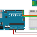
Step 4: Receiver Setup:
Step 5: Code:
RF Module Transmitter Code:
#include
const int ledPin = 13; char *data; void setup() { pinMode(ledPin,OUTPUT); vw_set_ptt_inverted(true); vw_set_tx_pin(12); vw_setup(2000); }
void loop() { data="1"; vw_send((uint8_t *)data, strlen(data)); vw_wait_tx(); digitalWrite(ledPin,HIGH); delay(2000); data="0"; vw_send((uint8_t *)data, strlen(data)); vw_wait_tx(); digitalWrite(ledPin,LOW); delay(2000); }
RF Module Receiver Code:
#include
const int ledPin = 13; const int datain = 11; void setup() { Serial.begin(9600); vw_set_ptt_inverted(true); vw_set_rx_pin(datain); vw_setup(2000); pinMode(ledPin, OUTPUT); vw_rx_start(); } void loop() { uint8_t buf[VW_MAX_MESSAGE_LEN]; uint8_t buflen = VW_MAX_MESSAGE_LEN; if (vw_get_message(buf, &buflen)) { Serial.print(buf[0]); if(buf[0]=='1') { digitalWrite(ledPin,HIGH); Serial.print(buf[0]); } if(buf[0]=='0') { digitalWrite(ledPin,LOW); Serial.print(buf[0]); } } }


