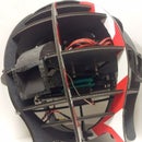
Introduction: Laser Spirograph Sound Visualizer (LSSV)
For this project we were tasked with building some kind of sound visualization device for a concert as part of an outreach activities for our research center. The briefs were three units of the device are needed and that the devices need to work over the span of an hour. They must not make any noise that might otherwise interfere with the musicians. Lets get to it!
Step 1: Prototypes
A common setup for a sound visualization device in many science demonstrations involves stretching balloon over a cylinder and sticking a mirror on the middle of the stretched balloon. Pressure changes due to sound would then cause the stretched balloon and thus the mirror to vibrate. Laser light shone on the mirror gets projected on to a surface, visualization the acoustic vibration
Since this configuration seem to be a tried and tested method of doing exactly what we wanted, we deemed it a good starting point for our prototype (Photo 1). What we observed was that the effect is good, but there are a few flaws with this method. Firstly, due to the stiffness and size of the stretched balloon, loud (problematic in a concert) and low frequency sound is needed to produced a noticeable pattern. Secondly, the projected pattern seems to be predominately straight lines.
Back to the drawing board. To address the first issue, we decided to use an audio transducer (Photo 2) to drive a small cantilever with an attached mirror instead. From our trail run (Video 1), we can see that there is only a very small range of frequency where the pattern is noticeable. The noise generated was also quite loud.
We need a way of modulating the angle of a mirror without generating much noise. After some brain storm we thought of the idea of a spirograph. A spirograph contains two spinning mirrors, titled at a slight angle. The first reflection creates a ring pattern, then the second mirror superimpose a spiral pattern. For out prototype (Photo 3), we broke out two cheapo usb powered fans and installed a variable resistors in series in the supply lines of each fan, allow us to adjust their rotation speed. The effect can be seen in Photo 4 and 5.
Next to electronically control the rotation speed of each motor, we used an Arduino compatible two channel motor shield. We wrote a small sketch that maps the ADC values from the analog pins to pwm commands to the motor shield. We found that the small brushed motors are not really responding fast enough to the input signal. Since there is not closed loop control of the rpm, the motor rotational speed fluctuate a lot when there is some transient load on it.
Thus we decided to try some rc plane brushless motors instead. At least for brushless motors, the rc servo signal is sort of proportional to the rotation speed of the motor. We replaced one of the brushed motor with a brushless one (Photo 6) and map the input audio signal to rc servo signal. The effect can be seen here (Video 2). The slow change in the pattern is due to the brush motor slightly stalling from the vibration of the brushless motor. Now we now we are on the right track.
Step 2: Design and Fabrication
Now that we have our game plan, we gotten the cheapest brushless motor and controller that we could find (1200 KV, 20A ESC). To speed up our build so that we can meet the deadline, we used optomechanics parts from out optics lab to complete the build.We used a 9i n x9 in optical breadboard fro the base, although any base would do the job equally well. We then 3D printed mirror holders that are tilted 5 degrees from the rotation axis and stuck mirrors on them using superglue.
A problem we faced was how to continuously supply the green laser pointer with power. We one to retain the outer casing for mounting purposes. For this we decided the make copper cylinders using a lathe that is similar in dimensions to an AAA battery. We drill a small hole at the end of the cylinder for the cable. The cable was then passed though a small hole drilled to the back cover, allowing us to power the laser pointer continuously.
We also fabricated simple Arduino shields (eagle cad file and sketch attached) that would act the interface for the input audio signal and output servo control. We also included a LM317 voltage regulator that will provide the necessary 1.5V from a 12V power supply to power the laser pointer. We intial chose a small surface mount package for the LM317, but is overheat readily and go into thermal shutdown. Thus were forced to botch in a large package that can be attached to the heat sink.
We then laser cut 3 mm thick clear acrylic to make into a lid that is 9 in x 9 in x 2.5 in. Finally we lined the inside with foam to try to cut out some of the high frequency sound from the motors.
Step 3: Showtime!
It was very hectic on the afternoon before the concert. We practically built the three units of the LSSV from scratch since the morning. At the venue, setup was a breeze, we just need plug in the power and the audio signal and we are done. The minor calibration that we need to make was to determine what is the peak signal amplitude from the audio amplifiers.
During the show the intensity of the laser pointers does drop a lot with like 10 mins of usage. So we decided to play along with it switch on and off the units at various section of the music.
Unfortunately we were not allow to take any photos and video during the concert. So after the concert we took one of the units and played around with it.


