Introduction: Light Play Set
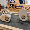
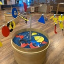
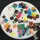
Light Play is an activity in the Tinkering Studio that lets you explore light, shadow, and motion using a variety of simple materials and light sources. Beginning with gently guided explorations of shadows, single and multiple light sources, three-dimensional objects and translucency, participants gain the proficiency and “light vocabulary” to express their ideas, and their creativity is sparked. They work toward building kinetic light and shadow vignettes, and eventually combine them into a collaborative installation.
This activity is about de-mystifying what “making art” means and looks like, and who is allowed to do so, by using familiar materials that create unfamiliar and evocative effects, and by manipulating an element that is literally everywhere: light itself.
In the Tinkering Studio we've worked to create a set of screens and lights that can allow participants to explore light and shadow without having to worry about the electrical connections. This instructable shows how we make our components for the museum floor, but if you are working in a classroom or at home we recommend that you use this only as a starting point and make the pieces in a way that works for you.
Step 1: This Is a Rough Guide
This is a guide to how to make the set that we use on the floor of the Exploratorium. Feel free to adapt and modify the materials and components to meet your needs. The most important thing is investigating light and shadows in a playful way.
For the Screens
You can use an translucent surface such as parchment or butcher paper for a cheaper, but more fragile screen. It might also be interesting to eliminate the screens entirely and create a shared light installation on a large white wall or ceiling.
For the Lights
It's possible to make or buy a variety of point source lights to experiment with light play. One easy way to create a good point light source is to unscrew the top of a mag light flashlight and remove the little plastic lens.
We look forward to see how people tweak and adjust these instructions to suit their needs so please share discoveries and innovations.
Step 2: Materials for Screens and Lights
For the Screens
semi-circle shaped piece of 1/4" plywood - (the size and shape of this piece can vary according to your needs. we cut a piece that would fit in a re-purposed cabinet)
HDPE screen natural 1/32"- (this should fit on the front of your base. if you can't find this specific material, look for any translucent surface)
http://www.tapplastics.com/product/plastics/plasti...
5 1"x2" pieces of 1/2" thick plywood - (these will form the feet for your base)
10 wood screws - (for attaching the feet)
2 L brackets - (these attach the screen to the platform)
2 copper nails
screw
p strap
4 small bolts
4 large bolts
8 nuts
8 washers
12V power adapter
http://www.amazon.com/Power-Adapter-Supply-2-1mm-C...
Female power pigtail lead
For the Lights
1 BuckToot 350mA - (this is a little "driver" that sends the right amount of consistent power to the lights)http://www.ledsupply.com/led-drivers/bucktoot-350m...
1 Bright LED (Warm White) - (you can also find other colors on the website. Follow the same instructions to make a red, green, and blue light for a nice addition to the set)
http://www.ledsupply.com/leds/cree-xpg2-indus-star...
1.5 in piece of Aluminum Tubing 1"OD .5"ID - (this serves as a heat sink for the LED. You can also find a standard heat sink, but we like this custom piece because it fits on the loc-line)
http://www.mcmaster.com/ part no. 9056K282
Snap-Loc Any-Which-Way Coolant Hose .25" ID - (this flexible tubing allows the light to move and adjust to various angles and directions).
http://www.mcmaster.com/ part no. 5307K49 - (we use a tri-piece to connect the loc-line to both the pine block and the power supply.
Snap-Loc Wye Inline .25"ID
http://www.mcmaster.com/ part. no 5307K62
HexaThermTape - (this is a special sticker that conducts the heat of the light to the heat sink).
http://www.ledsupply.com/accessories/hexatherm-tap...
P Strap
2 Copper Nails
2 Thumb Screws
1 Screw
Twisted pair wire
.25" block of pine
Alligator clip wires - (we used the alligator leads to connect the light to the powered base)
http://www.amazon.com/SMAKN-Colorful-Insulating-Alligator-Cable/dp/B00GDUK0J2/ref=sr_1_1?s=electronics&ie=UTF8&qid=1405618821&sr=1-1&keywords=alligator+clips
Step 3: Tools for Construction
To build the set, you will need the following general tools:
Glue Gun and Hot Melt Glue Stick
Soldering Iron and Solder
Wire Strippers
Cordless Drill
Wrench
Big drill bit
Small drill bit
Phillips driver bit
Black and Red Sharpies
And these specialized tools:
Loc-Line tool
Tap Wrench and Tap (4-40)
Step 4: Attach Feet to Platform
- Screw the 1" x 2" plywood pieces to the bottom of the board with 2 wood screws for each. This will elevate the board off the table and provide some room for the wire leads.
Step 5: Make Connections for Power
In the Tinkering Studio we like to be able to power the boards with either wall power using a 12V transformer or with a 9V battery pack so we've added 2 types of connection. The copper nails allow the board to be compatible with our circuit board set and add components like slow moving motors, fans, and toy parts to our light sculptures.
- Hammer the two copper nails in one corner of the board about 1 in apart.
- Drill two small holes in front of each nail
- Cut off the end of the connector and thread each wire through the holes
- Use a p-strap to attach the connector to the bottom of the board
- Flip the board over. Cut and strip the wires and solder them to the nails.
- Label the leads with positive and negative signs to match the pigtail.
Step 6: Attach the L Brackets to the Screen
- Line up L-Brackets to the screen and label where the holes go.
- Make the holes in the plastic. We used a leather punch but you can also use the drill.
- Attach the L-Bracket to the screen using the nuts and bolts.
- Repeat on other side.
Step 7: Attach Screen to the Base
- Place screen in desired location on the board and mark the locations on the board.
- Drill holes where you've placed the mark.
- Put the bolts through the L-brackets and tighten (and adjust feet in case of mistakes).
- Set screen aside and gather parts to construct light.
Step 8: Solder Wires to LED
Now it's time to make the light.
- Strip the ends of twisted wire and solder them to the leads on the super bright LED. Make sure to leave at least 12 in of the twisted wire connected to the light.
Step 9: Build the Arm for the LED
- Drill a small hole in the side of the aluminum tube and thread the wire through.
- Thread the wire through a straight length of the loc-line. Set aside one extra piece for mounting to the block.
- Press fit the small end of the loc-line into the end of the aluminum tube
- Thread the other side of the wire through the small end and the large end of the tri-piece of loc-line
- Use the loc-line tool to connect the tri-piece to the straight length of tubing.
Step 10: Attach LED to Heat Sink
You can attach the LED to the aluminum tube heat sink just with the heat sticker but for the wear and tear of the museum floor we needed it to be a little more sturdy. So we used a tap and tap wrench along with two 4-40 hex head cap screws (the same size as your tap) to more solidly attach the LED to the aluminum tubing.
- Place the LED in the right spot and mark two of the holes on the sides of the hexagon.
- Drill out the holes (make sure you use a drill bit that has a smaller diameter than your screws).
- Use the tap wrench to thread the holes. Go slow so that you don't break the tap. It also helps to use a cutting fluid and back up the tap every half turn or so.
- Attach the LED using the sticker.
- Secure the LED in place with the cap screws.
Step 11: Attach the BuckToot
- Solder the output ends of the buck toot to the twisted paired wires coming off of the arm. Be sure to keep track of the positive and negative and connect it the right way.
- Add electrical tape or heat shrink to the soldered connections
Step 12: Attach the Arm to the Base
- Drill a hole roughly in the center of your piece of 2" by 4" pine.
- Use the rubber mallet to gently pound one piece of loc-line into the wood.
- Press the small end of the tri-piece into the piece on the block.
- Attach the buck toot with the p-strap
- Pound two copper nails into the side of the block near the unconnected ends of the buck toot.
- Solder those wires to the nails.
- Use a dab of hot glue to affix the loose wires to the wood.
Step 13: Collect Interesting Materials
We like to collect a variety of everyday materials that will behave in interesting ways when light shines through it or reflects off it.
- Reflective Stuff - mylar (...), cristmas tree bulbs, mirrors, disco balls, sequined fabric
- Clear Shapes - party cups, plastic champagne flute, water bottles, bubble wrap, shower door plastic, plastic takeout container, plastic tubes and rods
- Shadow Objects - strawberry baskets, cheese grater, springs, mesh cups, feathers, cut paper, small toys, printed transparencies with patterns
- Colorful Filters - acrylic scraps, diacroic flims (...), iridescent cellophane,
- Lenses - prisms, flat lenses, old glasses, magnifying glass.
For construction we also like to use:
- Masking tape
- Dowels on bases for height
- Clothespins
- 2" by 4" blocks
Step 14: Power Up Your Board
Your board can be powered either with a 9 volt battery pack or with a 12 volt transformer.
Be sure to NEVER PLUG THE BOARD DIRECTLY TO THE WALL!
Battery Power - attach alligator clip leads to the battery pack (or use a 9V battery from your circuit board kit.
Transformer Power - plug the end of the power adapter into the pigtail plug on the bottom of the board.
Then attach the copper nails of the lights to the copper nails on the board. If it doesn't light try switching the wires because the LED only will work with one polarity. If it still doesn't light check your connections to maker sure that the places are supposed to be connected are and the ones that aren't supposed to be connected don't short circuit.
When the light turns on, put an object in front of it so that you can see the shadow on the screen...
Step 15: Experiment With Light and Shadow
Now that your light play kit is complete, it's time to experiment with all the materials that you have collected. Place a few objects and lights on the base and notice the shadows on the screens. Try moving objects closer and farther from the light source, see if you can mix colors using the filters, or notice how 3D objects move and change on a rotating platform powered by a slow moving motor.
You can create your own light and shadow vignette that is either abstract or narrative. Do you like the screen full of activity or would you rather create a minimalist art work? Experimenting with multiple light sources can also create interesting results.
In the tinkering studio, we often like to display a collection of screens all together in shelves or a cabinet to create a large-scale collaborative creation. If you are introducing this activity in a classroom or after school setting you might look for a way to allow participants to share their experiments with each other.
Share your discoveries with us at tinkering@exploratorium.edu. We'd love to see how this instructable gets changed and adapted by people in different settings.


