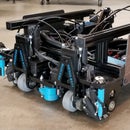
Introduction: Making FTC Robots Using Nontraditional Methods
Many teams who participate in FIRST Tech Challenge construct their robots using TETRIX parts which, although being easy to work with, do not allow for the greatest freedom or industrial engineering. Our team has made it our goal to avoid TETRIX parts altogether and create a robot from scratch, using a design first philosophy to do so. Although it can be a daunting task and requires a great deal of work, the process pays off greatly in terms of learning about the engineering process as well as the quality of the robot you can create. To inspire teams to take on unconventional approaches to FTC, and to help get them started on their engineering journey, we put together the following instructable to act as a general information guide for making nontraditional FTC robots.
Step 1: The "Design First" Philosophy
An important aspect of custom-making robots is the necessity to design what it is you want to make before attempting to fabricate it. While TETRIX-built robots are easy to take apart and can be used elsewhere, improperly designed custom parts are effectively useless and a waste of materials and time. Thus, you should take the time to design your part and verify that it is correctly designed before attempting to fabricate it.
The above video made by our team goes over the importance of designing robots first and the steps to the engineering cycle.
Step 2: Finding Parts and Tools
After conceptualizing your design, it is a good idea to make a list of the commercial off-the-shelf (COTS) parts, raw materials, and tools you think you will need. Taking note of what motors, screws, wheels, bearings, sensors, and tools you will need as early as possible will assure that you are not bottle-necked by a lack of resources later in the season.
A local hardware store is always a good place to start when buying COTS. Some good places from which our team has gotten COTS include:
- Ace Hardware - a hardware store with a great selection of parts and tools; has an online store and delivery service.
- McMaster-Carr - COTS, raw materials, and tools supplier; has an online store and delivery service.
- Amazon - Online store; sells most anything.
Above is a video our team made of us walking through our local Ace Hardware, going over the uses of various parts and tools.
Step 3: Designing Your Robot
In order to be able to fabricate your robot, you will need to design it. Luckily, there are a variety of computer aided design (CAD) software available to students for free. There are also a variety of resources available to learn how to use them, in the form of videos, written guides, and forum boards.
The following is a list of some different 3D CAD software - our team uses Fusion 360:
- Autodesk Fusion 360 - available for free for students and teachers.
- Rhino 3D - available for free for students and teachers.
- SOLIDWORKS - available for students whose schools have 40 networked seats or 100 networked seats.
Above is a video of our team discussing the advantages of using Fusion 360 to design your robot. These advantages includes its cloud service, the ease at which you can export models in various ways, the ease at which you can import models, and its stress test simulation tools.
Step 4: Fabrication Strategies and Options
Once you have created a design and verified its accuracy, it will be time to fabricate them. Before doing so, your team should make a workflow plan so that you are fabricating at an efficient pace; this is especially important for teams who have limited manufacturing resources, as these will become a bottleneck if time is not managed properly. Such management is known as process engineering, and the resources that teams should be aware of include:
- Machine resources - the availability of machines.
- Human resources - the availability of team members and their capacity to work on things.
- Raw resources - materials used for creating parts.
- Time resources - how effective time is being used; something ought to always be worked on.
There are several options when determining how you should create your part. The means which you can use to fabricate your designs are as follows:
- Computer aided manufacturing (CAM) - you can convert your designs into G-code, a programming language which can be read by Computer numerical control (CNC) machines; you can then use a CNC machine to mill out your part. Recommended for structural parts that will undergo a significant amount of force.
- 3D Printing - you can convert your design into an AMF or STL file to print them out using a 3D printing machine. Recommended for holsters for electronics or other parts that do not undergo a significant amount of force.
- Hand-making - using your 3D model or a drawing of the model as reference, you can determine the dimensions of your part and fabricate it by hand, if the part calls for it. Recommended for operations that cannot be milled or 3D printed or operations that do not require a great deal of accuracy.
Our team made a video demonstrating how to create a CAM operation using Fusion 360 and mill out a part using a CNC machine, shown above.


