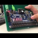
Introduction: Mirror Display
The goal of this project is to create the image display functionality of a Smart Mirror. The mirror is able to display forecasts (sunny, partly sunny, cloudy, windy, rain, thunder, and snow) and temperature values from -9999° to 9999°. Forecast and temperature values are hard coded as if to emulate them being parsed from a weather API.
The project uses a Zynq-Zybo-7000 board running FreeRTOS and uses Vivado 2018.2 to design and program the hardware.
Parts:
Zynq-Zybo-7000 (with FreeRTOS)
19" LCD (640x480)
VGA cable
12" x 18" acrylic mirror
Step 1: Configuring Vivado
Download Vivado 2018.2 from Xilinx and use the Webpack license. Launch Vivado and "Create New Project" and give it a name. Next select "RTL Project" and check "Do not specify sources at this time." When selecting a part, select "xc7z010clg400-1" and the hit "Finish" on the next page.
Step 2: Packaging VGA Driver IP
Add the vga_driver.sv file to the Design Sources. Next, click "Tools" and select "Create and Package New IP." Select "Package your current project." Then choose an IP location and "Include .xci files." Click "OK" on the popup and then "Finish."
On "Packaging Steps" go to "Review and Package" and select "Package IP."
Now the vga_driver should be available as an IP block.
Attachments
Step 3: Zynq IP
Under the "IP Integrator" section, select "Create Block Design." Add the "ZYNQ7 Processing System" and double click the block. Click "Import XPS Settings" and upload the ZYBO_zynq_def.xml file.
Next, under "PS-PL Configuration" open the dropdown for "AXI Non Secure Enablement" and check "M AXI GP0 interface."
Next, under "MIO Configuration" open the dropdown for "Application Processor Unit" and check "Timer 0" and "Watchdog."
Lastly, under "Clock Configuration" open the dropdown for "PL Fabric Clocks" and check "FCLK_CLK0" and at 100 MHz.
Attachments
Step 4: GPIO IP
Add two GPIO blocks to the Block Design. The GPIOs will be used to control the pixel address and the RGB components of the pixels. Configure the blocks as shown in the images above. Once you add and configure both blocks then click "Run Connection Automation."
GPIO 0 - Channel 1 controls the pixel address and Channel 2 controls the red color.
GPIO 1 - Channel 1 controls the green color and Channel 2 controls the blue color.
Step 5: Block Memory
Add a Block Memory Generator IP to the Block Design and configure as shown above. The pixel colors are written to memory addresses which are then read by the VGA driver. The address line is needs to match the amount of pixels that are being used so it needs to be 16 bits. The data in is also 16 bits since there are 16 color bits. We do not care about reading any acknowledge bits.
Step 6: Other IP
The attached pdf shows the completed Block Design. Add the missing IP and complete the connections. Also "Make Externals" for the VGA color outputs and the vertical and horizontal sync outputs.
xlconcat_0 - Concatenates the individual colors to form one 16 bit RGB signal that is fed into the Block RAM.
xlconcat_1 - Concatenates the column and row signals from the VGA driver and is fed into Port B of the Block RAM. This allows the VGA driver to read pixel color values.
VDD - Constant HIGH connected to the write enable of the Block RAM so that we can always right to it.
xlslice_0,1,2 - The slices are used to break the RGB signal into individual R, G, and B signals that can be fed into the VGA driver.
Once the Block Design is complete, generate an HDL wrapper and add the constraints file.
*Block Design is based off of the tutorial written by benlin1994*
Step 7: SDK
The code that runs this Block Design is included below. Init.c contains the functions that handle the drawing (forecasts, numbers, degree symbol, etc.). The main loop in main.c is what gets ran when the board is programmed. This loop sets the forecast and temperature values and then call the draw functions in init.c. It currently loops through all seven forecasts and displays one after the other. It is recommend that you add a break point at line 239 so you can see each image. The code is commented and will give you more information.
Step 8: Conclusion
To improve the current project, one could upload preload forecast images in the forms of COE files to Block Memory Generators. So instead of drawing the forecasts manually like we did in the C code, one could have the images read in. We attempted to do this but could not get it working. We were able to read pixel values and output them but it created messy images that were nothing like the ones we uploaded to the RAM. The Block Memory Generator datasheet is useful to read.
The project is essentially half a Smart Mirror since it is missing the internet connectivity aspect. Adding this would give a complete Smart Mirror.


