Introduction: Pan-Tilt Multi Servo Control
On this tutorial, we will explore how to control multiple servos using Python on a Raspberry Pi. Our goal will be a PAN/TILT mechanism to position a camera (a PiCam).
Here you can see how our final project will work:
Control Servo Control loop test:

Step 1: BoM - Bill of Material
Main parts:
- Raspberry Pi V3 - US$ 32.00
- 5 Megapixels 1080p Sensor OV5647 Mini Camera Video Module - US$ 13.00
- TowerPro SG90 9G 180 degrees Micro Servo (2 X)- US$ 4.00
- Mini Pan/Tilt Camera Platform Anti-Vibration Camera Mount w/ 2 Servos (*) - US$ 8.00
- Resistor 1K ohm (2X) - Optional
- Miscellaneous: metal parts, bands, etc (in case you will construct your Pan/Tilt mechanism)
(*) you can buy a complete Pan/Tilt platform with the servos or build your own.
Step 2: How PWM Works
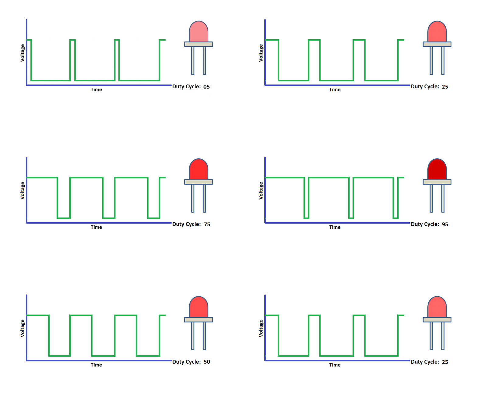
The Raspberry Pi has no analog output, but we can simulate this, using a PWM (Pulse Width Modulation) approach. What we will do is to generate a digital signal with a fixed frequency, where we will change the pulse train width, what will be "translated" as an "average" output voltage level as shown below:

We can use this "average" voltage level to control a LED brightness for example:

Note that what matters here is not the frequency itself, but the "Duty Cycle", that is the relation between the time that the puls is "high" divided by the wave period. For example, suppose that we will generating a 50Hz pulse frequency on one of our Raspberry Pi GPIO. The period (p) will the inverse of frequency or 20ms (1/f). If we want that our LED with a "half" bright, we must have a Duty Cycle of 50%, that means a "pulse" that will be "High" for 10ms.
This principle will be very important for us, to control our servo position, once the "Duty Cycle" will define the servo position as shown below:
Servo

Step 3: Installing the Hw
The servos will be connected to an external 5V supply, having their data pin (in my case, their yellow wiring) connect to Raspberry Pi GPIO as below:
- GPIO 17 ==> Tilt Servo
- GPIO 27 ==> Pan Servo
Do not forget to connect the GNDs together ==> Raspberry Pi - Servos - External Power Supply)
You can have as an option, a resistor of 1K ohm between Raspberry Pi GPIO and Server data input pin. This would protect your RPi in case of a servo problem.
Step 4: Servos Calibration
The first thing to do it is to confirm the main characteristics of your servos. In my case, I am using a Power Pro SG90.
From its datasheet, we can consider:
- Range: 180o
- Power Supply: 4.8V (external 5VDC as a USB power supply works fine)
- Working frequency: 50Hz (Period: 20 ms)
- Pulse width: from 1ms to 2ms
In theory, the servo will be on its
- Initial Position (0 degrees) when a pulse of 1ms is applied to its data terminal
- Neutral Position (90 degrees) when a pulse of 1.5 ms is applied to its data terminal
- Final Position (180 degrees) when a pulse of 2 ms is applied to its data terminal
To program a servo position using Python will be very important to know the correspondent "Duty Cycle" for the above positions, let's do some calculation:
- Initial Position ==> (0 degrees) Pulse width ==> 1ms ==> Duty Cycle = 1ms/20ms ==> 2.0%
- Neutral Position (90 degrees) Pulse width of 1.5 ms ==> Duty Cycle = 1.5ms/20ms ==> 7.5%
- Final Position (180 degrees) Pulse width of 2 ms ==> Duty Cycle = 2ms/20ms ==> 10%
So the Duty Cycle should vary on a range of 2 to 10 %.
Let's test the servos individually. For that, open your Raspberry terminal and launch your Python 3 shell editor as "sudo" (because of you should be a "super user" to handle with GPIOs) :
sudo python3
On Python Shell
>>>
Import the RPI.GPIO module and call it GPIO:
import RPi.GPIO as GPIO
Define which pin-numbering schemes you want to use (BCM or BOARD). I did this test with BOARD, so the pins that I used were the physical pins (GPIO 17 = Pin 11 and GPIO 27 Pin 13). Was easy for me to identify them and not make mistakes during the test (In the final program I will use BCM). Choose the one of your preference:
GPIO.setmode(GPIO.BOARD)
Define the servo pin that you are using:
tiltPin = 11
If Instead, you have used BCM scheme, the last 2 commands should be replaced by:
GPIO.setmode(GPIO.BCM)
tiltPin = 17
Now, we must specify that this pin will be an "output"
GPIO.setup(tiltPin, GPIO.OUT)
And, what will be the frequency generated on this pin, that for our servo will be 50Hz:
tilt = GPIO.PWM(tiltPin, 50)
Now, let's start generating a PWM signal on the pin with an initial duty cycle (we will keep it "0"):
tilt = start(0)
Now, you can enter different duty cycle values, observing the movement of your servo. Let's start with 2% and see what happens (we spect that the servo goes to "zero position"):
tilt.ChangeDutyCycle(2)
In my case, the servo went to zero position but when I changed the duty cycle to 3% i observed that the servo stayed in the same position, starting to move with duty cycles greater than 3%. So, 3% is my initial position (o degrees). The same happened with 10%, my servo went above this value, topping its end on 13%. So for this particular servo, the result was:
- 0 degree ==> duty cycle of 3%
- 90 degrees ==> duty cycle of 8%
- 180 degrees ==> duty cycle of 13%
After you finish your tests, you must stop the PWM and clean up the GPIOs:
tilt= stop()
GPIO.cleanup()
The above Terminal print screen shows the result for both of my servos (that has similar results). Your range can be different.
Step 5: Creating a Python Script
The PWM commands to be sent to our servo are in "duty cycles" as we saw on the last step. But usually, we must use "angle" in degrees as a parameter to control a servo. So, we must convert "angle" that is a more natural measurement to us in duty cycle as understandable by our Pi.
How to do it? Very simple! We know that duty cycle range goes from 3% to 13% and that this is equivalent to angles that will range from 0 to 180 degrees. Also, we know that those variations are linear, so we can construct a proportional schema as shown above. so, given an angle, we can have a correspondent duty cycle:
dutycycle = angle/18 + 3
Keep this formula. We will use it in the next code.
Let's create a Python script to execute the tests. Basically, we will repeat what we did before on Python Shell:
from time import sleep
import RPi.GPIO as GPIO
GPIO.setmode(GPIO.BCM)
GPIO.setwarnings(False)

def setServoAngle(servo, angle):
	pwm = GPIO.PWM(servo, 50)
	pwm.start(8)
	dutyCycle = angle / 18. + 3.
	pwm.ChangeDutyCycle(dutyCycle)
	sleep(0.3)
	pwm.stop()

if __name__ == '__main__':
	import sys
	servo = int(sys.argv[1])
	GPIO.setup(servo, GPIO.OUT)
	setServoAngle(servo, int(sys.argv[2]))
	GPIO.cleanup()
The core of above code is the function setServoAngle(servo, angle). This function receives as arguments, a servo GPIO number, and an angle value to where the servo must be positioned. Once the input of this function is "angle", we must convert it to duty cycle in percentage, using the formula developed before.
When the script is executed, you must enter as parameters, servo GPIO, and angle.
For example:
sudo python3 angleServoCtrl.py 17 45
The above command will position the servo connected on GPIO 17 with 45 degrees in "elevation". A similar command could be used for Pan Servo control (position to 45 degrees in "azimuth"):
sudo python angleServoCtrl.py 27 45
The file angleServoCtrl.py can be downloaded from my GitHub
Step 6: The Pan-Tilt Mechanism
The "Pan" servo will move "horizontally" our camera ("azimuth angle") and our "Tilt" servo will move it "vertically" (elevation angle).
The below picture shows how the Pan/Tilt mechanism works:

During our development we will not go to "extremes" and we will use our Pan/Tilt mechanism from 30 to 150 degrees only. This range will be enough to be used with a camera.
Step 7: The Pan-Tilt Mechanism - Mechanical Construction
Let's now, assembly our 2 servos as a Pan/Tilt mechanism. You can do 2 things here. Buy a Pan-Tilt platform mechanism as the one shown on the last step or build your own according to your necessities.
One example can be the one that I built, only strapping the servos one to another, and using small metal pieces from old toys as shown in the photos above.
Step 8: Electrical Pan/Tilt Assembly
Once you have your Pan/Tilt mechanism assembled, follow the photos for full electrical connection.
- Turn off your Pi.
- Do all electrical connections.
- Double check it.
- Power on your Pi first.
- If everything is OK, power your servos.
We will not explore on this tutorial how to set-up the camera, this will be explained on next tutorial.
Step 9: The Python Script
Let's create a Python Script to control both servos simultaneously:
from time import sleep
import RPi.GPIO as GPIO
GPIO.setmode(GPIO.BCM)
GPIO.setwarnings(False)

pan = 27
tilt = 17

GPIO.setup(tilt, GPIO.OUT) # white => TILT
GPIO.setup(pan, GPIO.OUT) # gray ==> PAN

def setServoAngle(servo, angle):
	assert angle >=30 and angle <= 150
	pwm = GPIO.PWM(servo, 50)
	pwm.start(8)
	dutyCycle = angle / 18. + 3.
	pwm.ChangeDutyCycle(dutyCycle)
	sleep(0.3)
	pwm.stop()

if __name__ == '__main__':
	import sys
	if len(sys.argv) == 1:
		setServoAngle(pan, 90)
		setServoAngle(tilt, 90)
	else:
		setServoAngle(pan, int(sys.argv[1])) # 30 ==> 90 (middle point) ==> 150
		setServoAngle(tilt, int(sys.argv[2])) # 30 ==> 90 (middle point) ==> 150
	GPIO.cleanup()
When the script is executed, you must enter as parameters, Pan angle and Tilt angle. For example:
sudo python3 servoCtrl.py 45 120
The above command will position the Pan/Tilt mechanism with 45 degrees in "azimuth" (Pan angle) and 120 degrees of "elevation" (Tilt Angle). Note that if no parameters are entered, the default will be both, pan and tilt angles set up to 90 degrees.
Below you can see some tests:

The servoCtrl.py file can be downloaded from my GitHub.
Step 10: Loop Test of Servers
Let's now create a Python Script to automatically test the full range of servos:
from time import sleep
import RPi.GPIO as GPIO
GPIO.setmode(GPIO.BCM)
GPIO.setwarnings(False)

pan = 27
tilt = 17

GPIO.setup(tilt, GPIO.OUT) # white => TILT
GPIO.setup(pan, GPIO.OUT) # gray ==> PAN

def setServoAngle(servo, angle):
	assert angle >=30 and angle <= 150
	pwm = GPIO.PWM(servo, 50)
	pwm.start(8)
	dutyCycle = angle / 18. + 3.
	pwm.ChangeDutyCycle(dutyCycle)
	sleep(0.3)
	pwm.stop()

if __name__ == '__main__':
    for i in range (30, 160, 15):
        setServoAngle(pan, i)
        setServoAngle(tilt, i)

    for i in range (150, 30, -15):
        setServoAngle(pan, i)
        setServoAngle(tilt, i)

    setServoAngle(pan, 100)
    setServoAngle(tilt, 90)
    GPIO.cleanup()
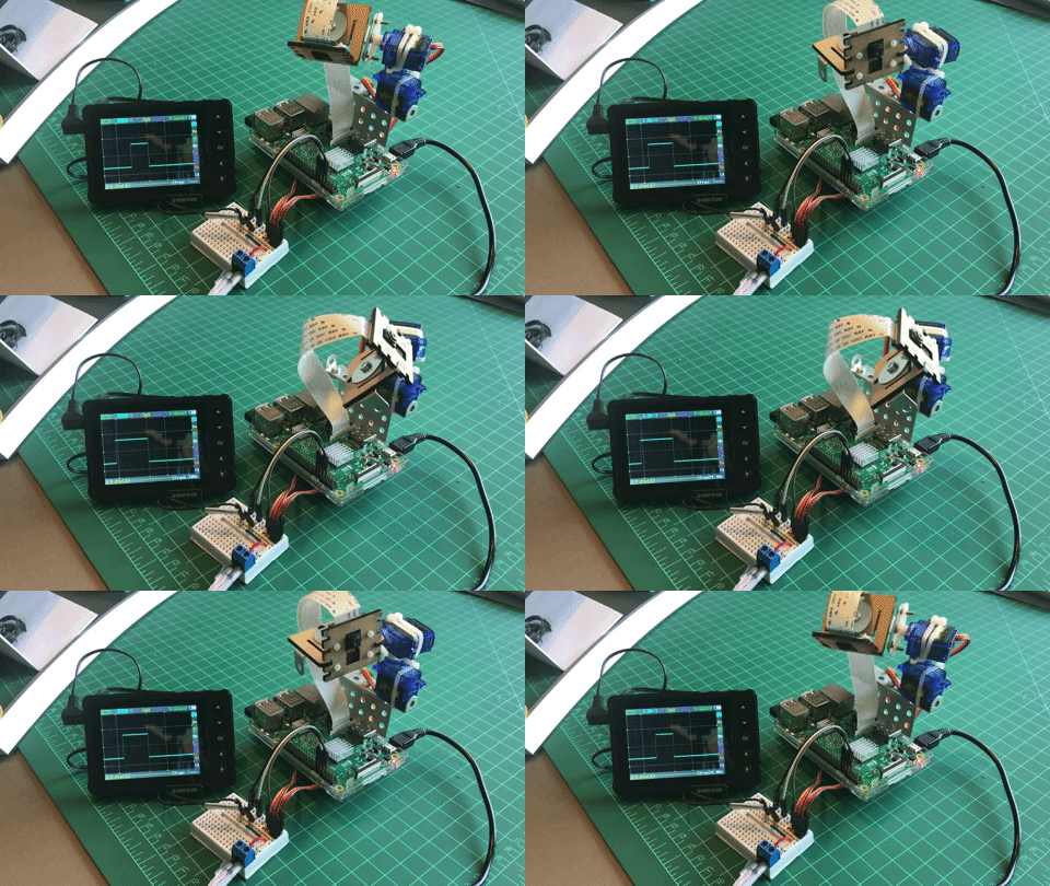
The program will execute automatically a loop from 30 to 150 degrees in both angles.
Below the result:
I connected an oscilloscope only to illustrate the PWM theory as explained before.

The above code, servoTest.py can be downloaded from my GitHub.
Step 11: Conclusion
As always, I hope this project can help others find their way into the exciting world of electronics!
For details and final code, please visit my GitHub depository: RPi-Pan-Tilt-Servo-Control
For more projects, please visit my blog: MJRoBot.org
Below a glimpse of my next tutorial:

Saludos from the south of the world!
See you in my next instructable!
Thank you,
Marcelo


