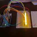
Introduction: Project 3 : Push Button and LED
This is the third instructable from my side. We have seen the simple LED Blink, Photo Resistor and now we are going to see Push Button in application with a LED. We are going to learn some new terms in Software Programming today.
It's also going to be a project in the simple, basic and beginner level project. Push Button are found almost everywhere in the laptop, computers, calculators, gaming arcades, keyboards and light. Now we will see its function with Arduino with an Led.
Step 1: What You Require?
The requirements for this program are the same as before but with just one new inclusion in it.
- Arduino Uno or Arduino Mega 2560 (They are the beginning boards of Arduino)
- Jumper Wires (Male to Male)
- Led
- Push Button
- Breadboard
- 10 K (more preferable) or 1k resistor
- Cable (To connect board with your Computer for uploading the Program)
- Arduino Program (Downloadable from https://www.arduino.cc/en/Main/Software
Step 2: Build Your Circuit and Know Why Is It Designed So?
Place a pushbutton in the breadboard. They should be properly fixed. The legs should tightly fixed or else it will not work. Put a 10k resistor to one leg on any coloumn. On the other end connect the hole through a jumper wire to 5v. The 5v power comes from the idea we used in 2nd Project of Photoresistor. Connect the leg of the button directly opposite to where the resistor is put to the one of the pins in the Pin Mode for the identification of the button. Then next connect one of the other leg with negative power from GND. Then make the LED setup as we did before.
Now lets understand how does this button work. Being a Middle School student myself I have learnt the Electric Circuits at school last year. The theory of working of the button I learned at school is the same for the Arduino.
We can understand its working through the circuit symbols. The second pic shows the circuit symbol of switches. The upper one shows unconnected or broken connection of the push button. At this time no electricity passes. But if we press then electricity passes and makes the joined legs.
Step 3: Now for the Software and Understanding It
const int buttonPin = 8;
const int ledPin = 9;
int buttonState = 0;
int flag=0;
void setup() {
pinMode(ledPin, OUTPUT);
pinMode(buttonPin, INPUT_PULLUP); }
void loop()
{ buttonState = digitalRead(buttonPin);
if (buttonState == LOW)
{ if ( flag == 0)
{ digitalWrite(ledPin, HIGH);
flag=1;
}
else if ( flag == 1){
digitalWrite(ledPin, LOW);
flag=0; } }
delay(200); }
Input Pull up and else if are the new terms we are going to learn today.
Input Pull Up: This example demonstrates the use of INPUT_PULLUP with pinMode(). It monitors the state of a switch by establishing serial communication between your Arduino and your computer.
Else if: It is actually almost the same as else.
buttonState=digitalRead(buttonPin) is a tool where the Arduino is commanded to find out if the input is being recieved from the button (buttonPin) by pushing (as we defined it as Input Pull Up).
The rest of the program is just like the one we did in the photo resistor. If any doubt in the program you can ask through the Comments.
Step 4: Congratulations
You have successfully made another project on the Arduino. If there are any doubts or questions please feel free to ask. Questions can be asked not only the instructables I posted but also other stuff related to Arduino.


