Introduction: Self-Balancing PT (homemade Segway)

This Instructable is intended to share my hobbyist project: a Self-Balancing Personal Transportation (SBPT), also known as "Homemade Segway". It is an interesting project requiring a minimal knowledge in electronics and some handcraft skills. All the components can be bought in internet and the mechanical parts assembly can be done in your home workshop.
The SBPT consists in a platform to stand on vertically with 2 side electrical motors powered by batteries. The controller algorithm ensure the balanced position to not fall forward or backward. The 2-wheeler motion is controlled by the rider with the tilt and the handle for the direction. Therefore additional electronical components like a controller, motor drive and acceleration/gyroscope sensor are required. The mechanical framework is made with material like wood because it is lightweight, electrically isolated and very easy to work for prototyping purpose. The description reflects the current status and will be updated with the coming optimizations and enhancement according to the readers’ comments. The way the hardware configuration and the software purpose are documented is to give you a reference which one you can modify to meet your needs. Finally, it is your homemade project!
Adrian Kundert
Step 1: Application’s Target Definition
The goal here is to state what we want to achieve with the SBPT. This will lead what and how the vehicle has to be build up. In my case, I wanted the following features:
- Enough powerful and rugged to ride outdoors even on gravel path
- At least 1 hour operation range
- Total cost less than 500€
- Wireless communication at debugging to get all motion freedom
- Data logging on a SD card for troubleshooting over a long period
Step 2: System Design

The schematic above shows the wiring of the main components as well the worm gear motor. The Arduino controller can be the Uno, Nano or the ATmega328 as single IC. The batteries are connected serial to get 24V which supplies the dual H Bridge for motors. This one is only powered as long the rider holds the ready button. In emergency case, the rider just release the push button to get unpowered the motors. The Arduino controller uses the serial communication in the “Packetized” mode at 38400 baud with the H-Bridge and the wireless module XBee. The tilt and steer are measured by an acceleration/gyroscope InvenSense MPU-6050 sensor in a “GY-521” on 2 separated breakout board and communicate with the Arduino by I2C. The tilt sensor (address 0x68) which is the most important is programmed to sense at every 20 ms and gives an interrupt to the Arduino. The second sensor (address 0x69) is pulled by the Arduino. Finally, the rider loaded limit switch is aimed to detect when the rider stands on the SBPT in order to activate the balancing algorithm.

Step 3: Framework Construction

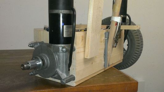


The wheels and gearboxed-motors are hold by screws into 3 pieces of wood assembled in a U form box. The handle is a wood stick hold by a bolt in the front wood piece. Very important is that the weight distribution SBPT is balanced when held vertically, which is the riding position. For this verification, the heavy parts like the batteries must be considered, otherwise it will be more difficult for the balancing algorithm.
In my case, the batteries are placed rear in the wood box to compensate the motor weight which in centered. At the remaining space between the batteries and the front of the wood box is placed the electronics components.
On handle is taped the “rider ready” push button. Sorry about the very prototype status with a lot of tape and Vise Grip usage.
Step 4: Electrical Wiring


The wiring in the wood box is done according to the system schematic. The Arduino pinout table gives you the wire connection to the sensors, h-bridge and switches.
The tilt sensor is mounted flat horizontally to get the x axe angle. However, the steer sensor is mounted vertically to get the left/right steer angle with the y axis.
Step 5: Testing and Tuning

Don’t forget: the motors can be powerful! Ensure the trial is done in a wide and safe area to not cause damage or injuries. It is recommended to wear protection pads and a helmet.
Important is to proceed step by step. Begin by programming the Arduino (download the source code), then verify the communication with the sensors and afterward with the H-Bridge. The Arduino Terminal can be used for debugging and to verify the working status. For example, the PID gains must be tuned because it depends of the motor mechanical and electrical proprietries.
The gains can be tuned with this typical method:
1. Kp is mainly for the balancing. Increase Kp till the balancing become instable, Ki and Kp remain 0. Reduce Kp a bit to get stable again.
2. Ki is for the acceleration/deceleration by the tilt. Increase Ki to get the right acceleration to avoid falling when tilting forward, Kp remain 0. The balancing should be now is stable.
3. Kd is used to compensate the integration and get again a stable the balancing.
In Terminal, you can get the differents commands by the command "?".
________________________________________________________________________________________
? - Help for the commands
p,i,d [value] - Set/Get PID gain, value between 0 to 255
r [value] - Force the motor speed, value between -127 to 127
v - Software version
________________________________________________________________________________________
With the command "p", you get the Kp. With the command "p 10", you set the Kp to 10.
Once the Arduino controller is powered, the sensors are initialized and finally the waiting state is reached. Pressing the push button will signal to the controller the SBPT has to be prepared by getting the vertical position by activating the motors forward or backward dependant the initial position. From this point, this button has to be held otherwise the motors are unpowered and the controller goes back in the waiting state. Once the vertical reached, the controller is waiting the signal from the “Rider Loaded” limit switch, normally pressed by the foot when get on the platform. When this happen, the balancing algorithm is launched and will activate the motors forward or backward to stay in a vertical position. Leaning forward will create a motion forward, and vice versa. Keep leaning will increase the motion speed. Leaning in the opposite side of the motion will decrease the speed. About the direction left or right, just move the handle in the desired direction.
Attachments

Step 6: Demo

Here you can watch a short video as a demo to see the dynamical behaviour of my SBPT. This should be the funniest step of all!