Introduction: Servo Deadband Correction
Analog servos require the pulse-width to change by up to 10 microseconds before they start to move. This represents an error of almost 2 degrees. [1]
This instructable explains how to significantly reduce the deadband errors in the servo plotter described in https://www.instructables.com/Servo-Plotter/
Images
- Photo 1 shows the orginal servo plotter
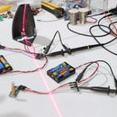
- The lower trace in photo2 shows two overlaid squares. One square is plotted clockwise (CW) ... the other is plotted counter-clockwise (CCW). Deadband is distorting the squares and causing the diagonals to separate.
- The upper trace in photo2 shows the improvement when deadband compensation is applied.
- The video shows servo plotter 2 in action ... note the deadband improvement
The cost of the push-switches for this project is less than $5.00
Notes
[1]
For a standard servo:
- 500uS produces 0 degrees
- 1000uS produces 90 degrees
- 1500uS produces 180 degrees
- 1 degree equates to (1500-500)/180uS = 5.5uS
- 10uS equates to 10/5.5 = 1.8 degrees
Step 1: Reducing Mechanical Errors
Photo 1 shows the penlift in instructable https://www.instructables.com/Servo-Plotter/.
This simple penlift has a serious problem ... the servo horn tends to displace plotter arm 2 sideways when it is raised and lowered.
Rotating the SG90 servo 90 degrees doesn’t fix the problem as the servo horn is now off-center causing arm2 to twist.
Arm 2 is replaced in Photos 2, 3, 4 with a length of 3mm aluminium extrusion to which an alternate design penlift is attached.
Only the pen touches the paper under its own weight ... the servo arms are no longer displaced.
Now that the mechanical errors have been minimised (there is still a tiny backlash in the gears) lets modify the circuit.
Step 2: Circuit Diagram
The circuit and parts are the same as for the plotter described in https://www.instructables.com/Servo-Plotter/ with the addition of two push-switches.
These push-switches allow you to increase/decrease the servo pulse widths under menu control.
The cost of the push-switches for this project is less than $5.00
Step 3: Installing the Software
Method:
- Copy the attached file “servo_plotter_10.ino” into an Arduino sketch and save it to a folder using the same name but without the .ino extension.
- Copy myServo.h into the folder you have just created. [1]
- Copy myServo.cpp into the folder you have just created. [1]
- Compile and upload “servo_plotter_10” to your Arduino.
- Set your Arduino “Serial Monitor” to 9600 bauds.
- The menu in photo should appear.
Caution:
[1]
The above files, myServo.h and myServo.cpp, are different from those of the same name in https://www.instructables.com/Servo-Plotter/
15 January 2022
Alternate software using a PCA9685 servo shield has been posted here https://www.instructables.com/ArduinoServo-Shield/
Step 4: Calibrating the Servos
Servo Arm 1
- Draw radials at 10 degree intervals as shown in photo 1
- Select menu option T4 ... numbers should start scolling on your monitor.
- Press the “decrease” button until the servo is fully left (0 degrees)
- Now press the “increase” button and record the microseconds every 10 degrees.
- If you overshoot press the decrease button and approach the overshot point in a CW direction.
- You should now have 19 measurements.
- Repeat the process, this time recording the pulsewidths every 10 degrees in a CCW direction.
- Enter these values into spreadsheet as shown in photo 2
- Subtract the readings at each 10 degrees interval
- Sum these readings and divide by 19 ... this your servo deadband.
- Record this reading as “deadband1” in the “servo_plotter_10.ino” file header.
- Record the CCW reading for 90 degrees in the “servo1_90” header variable.
- Record the CCW reading for 45 degree in the “servo1_45” header variable
- Press both buttons to return to the menu.
- Recompile the Arduino sketch.
Servo Arm 2
- Repeat Method 1 for servo arm two using menu item T5. [1]
- Since servo 2 is inverted 0 degrees is in the CW direction.
- Stop rotating before the arms collide ... just divide by a lesser number.
- Record the average deadband as “deadband2”
- Record the 90 degree CCW reading in the “servo2_90” header variable
- Record the 45 degree CCW reading in the “servo2_45” header variable
- Press both buttons to return to the menu.
- Recompile the Arduino sketch.
Penlift
- The values for the SG90 servo in the header are near enough
- Press menu item T2 (Pen Up) before attaching the servo horn vertically.
- Photo 3 shows a graph of the CW and CCW readings for servo 1.
Notes
[1]
You may need to position servo arm 1 and reposition the radials first.
Step 5: Theory
Analog servos convert the incoming pulse-width to a DC voltage. A linear potentiometer is attached to the output shaft. This potentiometer acts as a voltage divider. When the DC voltage equals the potentiometer voltage the servo stops.
Deadband is introduced to reduce the the stationary servo current and to stop the servo "hunting".
In order to move to the next position we need to increase/decrease the pulsewidth until the motor moves.
With this in mind my software converts the target angle to a pulse-width. If the target angle is less than the last_angle I subtract the deadband for that motor. If the target angle is equal or greater than the last_angle I add the deadband for that motor.
This has the effect of reducing the deadband.
So how does it work?
Assumptions:
- each target location is surrounded by a circle of deadband radius
- hobby servos stop whenever they enter a deadband circle
Let’s assume that the plotter (servo) is currently sitting at coordinate “Point1”.
Start = Point1 ............... (1)
Let’s get the servo moving by increasing the pulsewidth to “Point2+deadband”.
Target = Point2+deadband .................(2)
But a circle of radius “deadband” about the Target lies on Point2
Finish = (Point2 + deadband) – (deadband radius) = Point2 ..................(3)
(which is exactly what we want ... the deadband has been cancelled.)
You can verify this as follows:
- the plots improve if you add the deadband pulse-width to the target pulse-width
- subtracting rather than adding the deadband pulse-width degrades the plots
- doubling the amount of deadband causes the plots to “wiggle/oscillate” due to overshoot.
Step 6: Sample Plots
Images
- Photo1 shows overlaid squares with and without deadband compensation
- Photo 2 shows a “Hello World!” plot
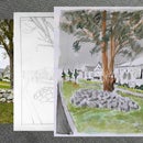
- A “Sobel” outline was obtained from photo 3 using my instructable https://www.instructables.com/CNC-Edge-Detection-...
- Photo 4 shows a partial plot of photo 3 in progress
- Photo 5 shows the finished outline.
The wiggles are possibly due to slight mechanical backlash in the servo gears.
Step 7: Summary
This instructables explains how to reduce the effects of servo deadband.
Improvements have been made to the plotter described in my instructable https://www.instructables.com/Servo-Plotter/. Specifically:
- Self supporting arms
- An improved penlift
- Deadband correction
Acceptable watercolor outlines can be produced using this servo plotter. [1]
The additional cost of parts for this plotter is less than $5.00
Note
[1]
Consider my CoreXY Plotter described in https://www.instructables.com/CoreXY-CNC-Plotter/... if you require high resolution plots.
Click here to view my other instructables.


