Introduction: The Haunted Carousel


This instructable was created in fulfillment of the project requirement of the Makecourse at the University of South Florida (www.makecourse.com).
Firstly, I don't take any responsibility for damage to your components or your health. Please be safe and practice smart habits when working with electricity and power tools.
I was inspired to make something with the Boos from Nintendo's Mario Bros during the Halloween season and this is what I came up with. Please enjoy.
The design is very simple, yet can be a pain to fabricate, but in this Instructable I’m going to show you how to build it.
Here are the parts I used:
- Arduino Kit .................................................................. http://makecourse.weebly.com/arduinokit.html
- 3/4 Inch x 3 Foot Round Aluminum (Buy best quality) https://www.lowes.com/pd/Steelworks-0-75-ft-Alumin...
- 3/8 Inch x 3 Foot Aluminum Rod ................................ https://www.lowes.com/pd/Steelworks-3-ft-x-3-8-in-...
- Purdy 1 Inch Brush (I didn't paint) .............................. https://www.lowes.com/pd/Purdy-XL-Dale-Polyester-N...
- 1/2-2-2 Birch Hardwood ............................................. https://www.lowes.com/pd/1-2-in-Birch-Plywood-Appl...
- Hot Glue Sticks .......................................................... https://www.lowes.com/pd/Arrow-24-Piece-0-5-in-Gen...
- Paint 3 Colors (buy 3, Red Green and Black) ............ https://www.lowes.com/pd/Valspar-6009-7-Vegas-Gree...
- Bronze Flange Bearing x 4 ........................................ https://www.lowes.com/pd/Hillman-1-Count-0-433-in-...
- 3/4 Inch x 2 Foot Pipe SCH40 ................................... https://www.lowes.com/pd/Charlotte-Pipe-3-4-in-x-2...
- 1/4 Inch x 36 Inch Round Oak x 2 ............................. https://www.lowes.com/pd/Madison-Mill-Round-Wood-O...
- White Push Axle x 8 .................................................. https://www.lowes.com/pd/Hillman-1-4-in-Zinc-Plate...
- Metric Socket Cap Screw M3-.5X6MM ..................... https://www.homedepot.com/p/Everbilt-M3-0-5-x-6-mm...
- Metric Socket Cap Screw M3-.5X20MM ................... https://www.homedepot.com/p/Everbilt-M3-0-5-x-20-m...
- 16 Inch Bucket .......................................................... http://www.acehardware.com/product/index.jsp?produ...
- Hook up Wire Kit ....................................................... https://www.amazon.com/gp/product/B00B4ZQ3L0/ref=o...
- 12V, 100 RPM motor, 6MM Shaft .............................. https://www.amazon.com/gp/product/B01KTZXZ1G/ref=o...
- 12V, 200 RPM motor, 6MM Shaft ............................. https://www.amazon.com/gp/product/B01KTXRB90/ref=o...
- Motor Hubs 6MM Shaft, 2-Pack ............................... https://www.amazon.com/gp/product/B00B887FX8/ref=o...
- 9V Batteries, 8-Pack ................................................ https://www.amazon.com/gp/product/B00MH4QM1S/ref=o...
- On/Off Switches, Circular, 10-Pack ......................... https://www.amazon.com/gp/product/B01ALINJ94/ref=o...
- 2 x Motor Mounting .................................................. https://www.amazon.com/gp/product/B00TK0X03U/ref=o...
- 2" Wheel x 3/4" Width For 1/4" Axle ........................ https://www.amazon.com/gp/product/B00K5S4U8K/ref=o...
- Motor Controller ...................................................... https://www.amazon.com/gp/product/B00CAG6GX2/ref=o...
- Voltage Regulator, Step Down Module, 6-Pack ...... https://www.amazon.com/gp/product/B07415DBF5/ref=o...
- 9V Battery Cable Connectors ................................. https://www.amazon.com/gp/product/B00GN7VS4Q/ref=o...
- Needle Roller Bearing, 3/4" ID, 1" OD, 5/8" Width . https://www.amazon.com/gp/product/B006KT1B80/ref=o...
- Styrofoam 2" thick x 4ft x 4ft
- Aluminum Tape
- Wood screws
- PLA for 3D Printers https://www.amazon.com/gp/product/B00J0ECR5I/ref=o...
These are the types of tools I used:
- Cordless drill
- Various bits
- Sawzall
- Jigsaw
- Chisels
- Liquid Nail
- Hot glue gun
- Soldering Iron
- Ruler
- Marker
- 3D Printer
- Machine shop: Lathe and Mill
Let's build it!
Step 1: The Design and Theory

The design I came up with utilizes:
1.Basic A/C compressor theory.
o The rod is moved up and down while revolving due to the cam plate spinning eccentrically below it.
----------> We will use this system to make the Boos move up and down.
2.Basic friction/gear theory.
o The wheel is mounted inside of the base and spins the whole carousel.
----------> Since the wheel is spinning and it is frictionally attached to the base.
These allow the relative motions between the spinning of the carousel and the Boos up and down movement to be controlled independently.
Step 2: Exploded View

This can be used as a reference for building the assembly.
I modeled it such that the way it explodes is simply the reverse of installation.
Step 3: Assembly Drawing With BOM

Here you can see each part and get a rough idea of the assembly.
It is advised to watch the previously posted exploded view animation.
Notes:
- The roller bearing is press fitted into the mounting board and is hot glued.
- The Rotary_Shaft_Swash_Plate is press fitted onto the Swash Plate.
- The Swash_Shaft_Insert is press fitted into the Rotary_Shaft_Swash_Plate.
- The Rotary Shaft is attached to the Carousel_Base with a block and glue.
- The Rod_Base_to_Top parts are fitted with the white axles and hot glued.
- The Boos are simply press fitted into the Smooth Rods.
- The 12V motors are connected to their brackets and respective positions.
Further detail on assembling The Haunted Carousel will be discussed next.
Step 4: Assembling the Haunted Carousel

Now let's take a look at how I fabricated these parts.
***For reference I have included my Solidworks Files***
***They can be found at the bottom of this section***
I started with making the top part of the carousel using styrofoam.
- I outlined a 16" circle and jigsawed two large 2" thick pieces.
- I then used liquid nail to glue them together overnight.
- I used a chisel to hollow out the center leaving 2" all around.
- I drilled a 1" hole through the center for the PVC rotary shaft.
- Lastly I used aluminum tape to reinforce the structure.
Next I took the large blue bucket and cut off the bottom 4" for the base.
- Start by marking holes for the 1" rotary shaft, the 1/4" oak rods (8), and the 3/8" flange bearings (4). This should be done with a ruler and a marker.
- Cut the oak rods into quarters and place them in the holes.
- Fortify the rods with the white push nuts and apply hot glue.
- Then make holes in the styrofoam to allow the rods to connect.
- Lastly, press the flange bearings into their holes with some hot glue.
Now is a good time to start 3D printing.
- There are 4 small Boos and one big one
- They can be printed with the standard infill
- May want to have them professionally done
- The swash plate should be printed in half and joined after printing.
- A stronger infill is required, >50%
- Print the Swash_Plate_Rotary_Shaft coupler
- Make it accurate and strong
Not a bad time to hit the machine shop either.
- Take the 2" wheel and have them shave off the center axle until flush.
- If they can make holes for the hub on the wheel, do it now.
- Cut the 3/8" rods for the boos - 4 x 4" length and round the bottoms.
- Attach the hub to the motor shaft and tighten the set screws.
- Align the hub to the inner shaft of the wheel and screw in the hubbed wheel.
While printing, I took the Birch hardwood and cut out a 21" circle.
- Carefully drill out a 1" hole in the center, roughly 3/4 through the hardwood.
- Then with a 1/2" bit, drill all the way through, making sure it's centered.
- Press the roller bearing into the hole and level it with a level.
- Apply hot glue on the outside to ensure that the bearing remains level.
Bringing things together, aligning the 100 RPM motor.
- With the 3D printed swash plate, press it onto the rotary shaft.
- Also press fitt the 3D printed coupler into the bottom of the rotary shaft.
- Place the rotary shaft + coupler into the bearing.
- Take the motor bracket and apply set pins to the motor.
- Press the motor shaft into the coupler from the bottom of the board.
- Outline the bracket using a pencil.
- Remove the motor from the bracket.
- Place just the bracket on the outline and mark the 8 mounting holes.
- Remove the bracket and drill the holes for the bolts, through the glue.
- Attach the bracket + motor to the coupler and screw the bolts in.
Aligning and Mounting the 200 RPM motor.
- Telescope the rods together now and see the assembly coming together.
- Outline the base (blue bucket) with a pencil onto the hardwood.
- Grab a piece of 4"x2"x1" wood (a wooden stake works well)
- Cut it as shown in the CAD files where it is ~7 degrees on the bottom.
- Mount the bracket and the motor with the hubbed wheel to the mount.
- Using the outline, place the wooden mount inside the base and outline it.
- Take the blue base off of the assembly and drill holes for the mount.
- Now take wood screws and mount the motor.
Getting the small Boos onto their shafts
- Drill out the bottoms to clean them up and press the smooth rods in.
- They are now ready to be placed into the flange bearings.
- Now you can spin the assembly by hand and see everything move!
Canvassing the top of the carousel and placing the large Boo.
- Cut out a circular wavy pattern and make a hold in the center.
- Simply hot glue the inside of the hole to the PVC rotary shaft.
- Place a frictionless rod down the center of the Swash_Plate_Rotary_Shaft
- Glue the Boo to a wine cork and press into the frictionless rod.
- If you want the big Boo to rotate, forget the frictionless rod.
Painting
- Since I didn't paint, I will leave it to your own discretion.
- Just use masking tape and have fun!
Now refer to the wiring section of this Instructable
- All that is left is to wire the motors and get the potentiometers to work.
For Reference here are some photos of what my sub assemblies look like:
This is the bottom of the base, showing the push nuts and flange bearings.
This is a side shot showing the view of the power switch.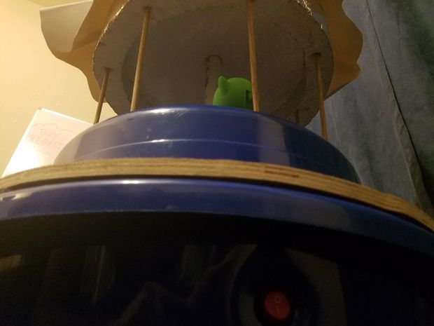
This shows the swash plate rotary bar connected to the bearing (w/ coupler) and a PVC stabilizer added for extra support.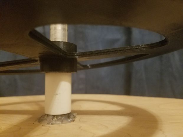
This is two of the three sub assemblies connected.
This is under the mounting board, showing the control box.

Attachments

Step 5: Wiring the Arduino and Components

The wiring process in order:
- 2 x 9V Batteries in Series.
- On/Off Switch between one of the battery leads.
- Step down Regulator from 18V to 14V.
- Into Arduino via adapter.
- Power both sides of breadboard with 5V and GND.
- Attach Pots 1 and 2 to Analog pins 1 and 3 respectively.
- Connect the L298N controller to Arduino (Vin, GND, PWM, and In1 to In4).
- Wire the motors to the controller.
- Attach the LCD screen via the I2C bus (VCC, GND, SCL, and SDA).
Notes:
- Calibrate the voltage regulator using a multimeter to set the desired output.
- In1 through In4 are needed to set the direction of spin of the motor.
Step 6: Arduino C++ Code (Header and Main)
The Arduino C++ code is attached.
Inside you will find the commented code and should be pretty straightforward.
Make sure to reference both my circuit layout, and the code to wire it correctly.
Note:
- Place the attached I2C library into the libraries folder of the Arduino app.
Step 7: Operating the Haunted Carousel
At this point we just get to have some fun with The Haunted Carousel!
- Adjusting Potentiometer one adjusts the speed of the main frictional motor from 0 to 200 rpms.
- Adjusting Potentiometer 2 adjusts the speed of the cam plate and thus the speed of the Boos.
Have fun and thank you for checking out my Instructable!