Introduction: Water Pump ESP-01 Timer Switch With Water Sensor
This project builds on the ESP-01 Timer Switch to automate the pumping of water for the house supply.
The water supply for a suburb of Delhi, India, is only available between 2am and 3am each day and so the water needs to be pumped up into a home tank, ~7m above ground level, to supply water for the following day. The situation is complicated by the fact that i) the water is not always available at exactly 2am and ii) the supply is some 1.5 m under concrete, below the pump.
The current process is to wake up at 2am each day and turn the pump on. Then check after 10min that water is pumping. That is, is there is a water supply and the pump has sucked up water from main. If there is no water after 10mins, turn the pump off for 15min and try again. There is a float switch on tank to turn the pump off once the tank is full.
Supplies
Parts as listed in ESP-01 Timer Switch with the additional parts
Water sensor – XKC-Y25 NPN Intelligent Non-Contact Liquid Water Level Sensor ~ Indian Rupee 549.
Step 1: Existing System
The existing control system is shown above (pdf)
When the remote controlled (RF) switch is operated, the pump runs until the water tank is full.
Step 2: Revised System With ESP-01 Timer Switch and Water Sensor
This project adds the ESP-01 Timer Switch and a water sensor to automate the running / stopping of the pump to fill the water tank.
In this system, the pump is enabled between 2am and 3am as set by the Timer Switch. The modified code in the ESP01 Timer Switch runs the pump for 10mins and then checks that water sensors has detected water in the inlet pipe to the pump. If no water is detected then the code turns the pump off for 15mins and tries again.
The revised system is shown below (pdf).
Step 3: Operation
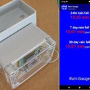
A new front web page gives the current status of the system and is refreshed every 5secs.
The timer's previous index.html is now timer.html and is only updated once every 2mins
Step 4: Programming the ESP-01S or ESP-01
See ESP-01 Timer Switch – Programming the ESP-01S or ESP-01 for how to setup the programming system. The same set of libraries is used for both the projects.
The code for this version of the timer switch with the water sensor and pump cycling is in ESP8266_waterPump_timer.zip. That code has the Delhi timezone set as the default. The libraries needed are the same as the ESP-01 Timer Switch and are contained in this libraries.zip
Compile and upload the sketch to the ESP-01 using the under “Erase Flash” select “All Flash Contents” option and then upload the webpages with the ESP8266 LittleFS Data Upload option.
Remember to close the Arduino Serial Monitor if it is open, before using ESP8266 LittleFS Data Upload, otherwise the upload can fail.
See the ESP-01 Timer Switch for how to connect to your WiFi network and how to set your time zone.
The RX pin on the ESP-01 is used as an input as described in ESP-01 and ESP-01S How program and use the Pins and Leds This still leaves the TX pin available to output debug messages when connected to the programmer.
This particular Water Sensor model has an open-collector (NPN) output and so does not need any level translation to connect to the 3V3 ESP-01 RX input.
Conclusion
The project is an extension of the ESP-01 Timer Switch which adds a water sensor input and code to cycle the water pump if water is not available. This automates what is otherwise a tiring job needing to be performed at 2am every morning of turning the pump on and checking after 10min that water is pumping. If not turning the pump off for 15mins and trying again.


