Introduction: Wiring the KFB2.0 3D Printer Controller
The KFB2.0 controller is an interesting little board, that caught my attention for it's size and price. It's less than $20 ($18.59 to be exact on Amazon.com: http://amzn.to/2FBSghi ) and about half the size in height compared to the RAMPS 1.4 (Stacked) kit.
It does lack some serious documentation, which is mitigated by the fact that it's basically a RAMPS 1.4 all-in-one on one board. Same 8 bit arduino chip and all the same pin configurations.
It does come with a few extra's like a 5v and 12v dedicated output (RAMPS only has the 12V and you can borrow 5V from elsewhere on the board).
You can also put more juice through the KFB2.0. It can take 12-40volts. Should you choose to go with a 24 Volt power supply make sure your heated bed and hot-end heater cartridge can handle the extra 12 volts.
It comes with 4 power outputs but in all honesty I've struggled (and lost) getting the 4th under control.
If you're deciding to go with the TMC2130 (see my instructable and results on that one here) you'r in luck as the dedicated ICSP connector will prevent you from having to solder on extra pins to share with the card reader.
The other difference with the RAMPS 1.4 is the connectors. the KFB2.0 uses all JST-XHP 2.54 connectors so bring out the crimping tools (or buy proper wires).
Update 1/25/2019: as part of a series on how to build the C3Dt/c 3D Printer, I pre-released a video on wiring the KFB2.0 (step by step). Check it out at: https://youtu.be/3WxL5Wdu-XY
Step 1: Parts Required
I have used the KFB2.0 board on 2 of my printers now (on you can find here) and am pleased with the way it operates.
The KFB2.0: $18.59 http://amzn.to/2Gk9qBi
Here's a list of all the items I have attached to the KFB2.0
Nema 17 1.7A (5 pack) http://amzn.to/2E3gvYc
Mk8 Extruder
full direct exturer $36.99 http://amzn.to/2E3gvYc
Extruder Frame only $8.99 http://amzn.to/2FL3hAc
V6 Hotend (12V): $18.99 http://amzn.to/2HoEXS0
For end stop control you can go with two options (I will discuss wiring for both):
The fully wired Limit switch (with cables): $7.98 http://amzn.to/2E3gvYc
The simple Micro Switch: $8.99 http://amzn.to/2E3gvYc
Stepper Cables: $8.59 http://amzn.to/2FHuALR (JSP HX2.54, which fit the KFB2.0)
12V/30Amp Power supply 19.98: http://amzn.to/2E3gvYc
Heated Bed $31.99 (optional but will describe wiring) http://amzn.to/2E3gvYc
Thermistors $8.99 http://amzn.to/2FtRvux
LCD 12864 $14.99 http://amzn.to/2HoEz60
Stepper Drivers $9.99 http://amzn.to/2FKdRYd
Fans. I'm a huge fan of the Noctua Fans. They are a bit pricier but worth the SUPER quiet:
12Volt: $13.95 http://amzn.to/2FDoyss
5Volt: $13.95: http://amzn.to/2p8JZdO
(If you want to go with the TMC2130, I recommend getting the real deal from trinamic waterott through Filastruder.com)
Step 2: Assembling the KFB2.0
Before adding the steppers, add 3 of the jumpers underneath each of the steppers. This will enable 1/16h micro stepping for the A4988 and DRV8825 drivers (not necessary for the TMC21xx drivers)
Adding the Stepper drivers does take some special care. MAKE SURE your drivers are oriented properly. The pins instructions are on the back of the board but I've add an image to show them on top. Your stepper boards should have the corresponding pin names. To keep it simple, align DIR and GND on the drivers to the board.
for the A4988 drivers this means the little pot meter is on the same side as the USB PORT
for DRV8825 and TMC2130 the pot meter points in the opposite direction
Step 3: Wiring the KFB2.0
Wiring the KFB2.0 is very similar to the RAMPS 1.4. As a matter of fact in the Software it is configured as a RAMPS 1.4 configuration. Most of the pins are connected identical to RAMPS.
One of the downsides to the KFB2.0 is that a lot of the useful information is printed on the back of the board. Take note of that before you bolt it on to something.
The first image above pretty much explains it all. Power (12-24V) goes in at the small green connector. Polarity IS IMPORTANT. Make sure positive connects to positive. The rest of the connections are discussed in the next steps.
Step 4: Connecting the Fans
-There are three FAN outputs.
The green connector with the Fan written next to is is the controllable fan that generally is referred to as the parts-fan. It is controlled variably by the software and cools the last layer of filament deposited.
There's a 5V fan output and a 12-24V fan output. It generally connects to the fan that is attached to your hot-end heat sync. This one starts running when you power up the board.
ALL FANS have a red and black wire. Polarity matters, make sure positive is connected to positive.
I'm a huge fan (no pun intended) of the Noctua fans. They are incredibly quiet. They come in both 12 volt and 5 Volt version.
If you have any plans of using auto bed leveling, I recommend using a 5 Volt fan as it will leave the 12 Volt connector for the proximity sensor used in Auto bed leveling.
Step 5: Connecting the Heaters
This boards has three outputs for heaters.
Hot Bed (Heated Bed)
Heater0 (primary extruder)
Heater1 (second extruder)
-The Hot bed and Heater0 outputs speak for themselves. They don't care about polarity but make sure you use wire of proper gauge (14-16) as these carry a lot of Amps).
-Heater1 is not as straight forward. If you have double extruders you should connect the second one to this output but; I have not been able to get it to work. I've tried tracing its pins back to the board but even after doing so I could not get it powered up.
I'll keep you posted if I ever succeed.
For each heater there would be a corresponding Thermistor that notifies the board of the actual temperature.
The thermistor for the extuder connects to TEMP0
The thermistor for the heated bed connects to TEMP-BED
Polarity does not matter for these connections.
Step 6: Connecting the End Stops (Maketbot Style)
If you are using the most commonly used end stops "Makerbot Designed Mechanical Endstop Kit", it comes with little circuit board and wiring. It will light up an LED when triggered.
There are 3 wires coming from the end stop: RED/BLACK/GREEN
IMPORTANT: make sure the wires correspond with the image above.
If you have to crimp your own connectors make sure the RED wire is on the "inside" towards the center of the board.
Reversing the wires I believe fry parts of your board.
Step 7: Connecting the End Stops (Micro Switches)
If you forego the fancy Makerbot Switch (don't do it for the price, it's generally more about the size of the sensor) and instead go with a micro switch it's my experience wiring is a bit easier. You really only need two wires.
Solder the wire to the two outside pins of the Micro switch and connect them to the GND Signal pin on the ramps.
These are the two pins towards the outside of the board (GND and SIGNAL). Since in this configuration the switch only breaks/closes the circuit, it doesn't really matter which wire goes to the Minus/Signal. DO NOT connect either of the wires to the VCC!!
Since in this configuration the connection is open you might have to flip the configuration in the Marlin software to reverse the signal.
#define X_MIN_ENDSTOP_INVERTING true // set to true to invert the logic of the endstop.
#define Y_MIN_ENDSTOP_INVERTING true // set to true to invert the logic of the endstop.
#define Z_MIN_ENDSTOP_INVERTING true // set to true to invert the logic of the endstop.
Step 8: Testing the Switch and Changing Marlin Accordingly
The following video shows me testing my Makerbot end stops but the principal remains the same
if the status flips from open to triggered when testing but starts in TRIGGERED mode when not depressed you'll need to reverse the setting in Marlin (configuration.h).
// Mechanical endstop with COM to ground and NC to Signal uses "false" here (most common setup).<br>#define X_MIN_ENDSTOP_INVERTING true // set to true to invert the logic of the endstop.
#define Y_MIN_ENDSTOP_INVERTING true // set to true to invert the logic of the endstop.
#define Z_MIN_ENDSTOP_INVERTING true // set to true to invert the logic of the endstop.
#define X_MAX_ENDSTOP_INVERTING false // set to true to invert the logic of the endstop.
#define Y_MAX_ENDSTOP_INVERTING false // set to true to invert the logic of the endstop.
#define Z_MAX_ENDSTOP_INVERTING true // set to true to invert the logic of the endstop.
#define Z_MIN_PROBE_ENDSTOP_INVERTING true // set to true to invert the logic of the probe.
Step 9: Setting Up the Software
I won't go into setting up the software in this instructable other than to say that the KFB2.0 runs Marlin 1.1.x and corresponds to the RAMPS_14_EFB.
In your configuration.h select the BOARD_RAMPS_14_EFB if you use a controlled fan and heated bed
// The following define selects which electronics board you have.<br>// Please choose the name from boards.h that matches your setup
#ifndef MOTHERBOARD
  #define MOTHERBOARD BOARD_RAMPS_14_EFB
#endif
It has been brought to my attention that you can also choose the BOARD_MKS_GEN_L as an option (it adds the Pin 7 for the additional mosfet (I have not tried this yet). MKS_GEN_L in fact is 99.9% RAMPS.
#if HOTENDS > 2 || E_STEPPERS > 2<br>  #error "MKS GEN L supports up to 2 hotends / E-steppers. Comment out this line to continue."
#endif<br>#define BOARD_NAME "MKS GEN L"
// Heaters / Fans
//
// Power outputs EFBF or EFBE
#define MOSFET_D_PIN 7

<br>#include "pins_RAMPS.h"
// The following define selects which electronics board you have.<br>// Please choose the name from boards.h that matches your setup<br>#ifndef MOTHERBOARD
  #define MOTHERBOARD BOARD_MKS_GEN_L
#endif
Step 10: Connecting LCD
The LCD connects to the two EXP1 and EXP2 connectors on the board via the 2 flat cables that most likely came with your LCD unit. You're LCD board will have the corresponding EXP1 and EXP2 on the back.
That's really all there is to it.
NOTE: Several reviewers for the KFB2.0 have complained that the LCD connectors are on backward, requiring them to cut of the notches from their cables. I won't dismiss this, but I've used 3 boards (ordered on different occasions) and have not found this to be a problem.
Step 11: Conclusion
The KFB2.0 is nothing fancy but it packs more than a traditional RAMPS 1.4 board and comes at a very reasonable price.
I currently have two printers running the KFB2.0 and have had no issues yet (at least not with the board).
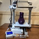
Both of these printers are fully explained here on instructables.com at
https://www.instructables.com/id/3D-Printer-Cantil...
https://www.instructables.com/id/3D-Printer-Cantil...
Let me know if I missed something, screwed up something or should add more for clarification.
Most product links are affiliate links so if you do need to purchase some items, please use those links. I'll make a few pennies.
If you would like to the instructables coming consider supporting me at patreon.com. Writing and testing all this doesn't just take time. I have to buy the parts as well. Thank you!!


