Introduction: 2M Moxon Antenna
I tried my first contest recently (RSGB 2M UKAC) and really enjoyed myself, although I realised just how restrictive my J-Pole antenna was when it comes to SSB and directionality... so I build this little moxon antenna using details provided by G0KYA's build, however the Moxon Antenna Project website he mentions no longer seems to be working I managed to fill in the gaps.
The construction is very simple with the antenna frame being made from 20mm electrical conduit and a few 3-way junction boxes, the antenna itself is made from single core 0.7mm insulated wire because I happened to have 3 rolls of it! Any kind of wire would subsitute here.
Step 1: Materials & Tools
Building materials:
1x 20mm electrical conduit (3M length)
2x 20mm 3-Way round junctions
1x 20mm 3-Way inspection junction
2x 30mm soft flat plastic*
1x SO239 / N-Type / ChocBlock
1x 3M of coated or uncoated wire
Tools:
- Junior Hacksaw
- Tape Measure
- PVC Solvent (or somekind of glue)
- Sandpaper
- Soldering Iron
* Any kind of isolating material can be used, such as materials from plastic bottles
Step 2: Design
A: 275.7mm
B: 746.2mm
C: 103.7mm
D: 29.8mm
E: 142.2mm
The construction itself is very simple; measure and cut all pieces to length, sand down the ends lighty to remove any burr, apply solvent and pressure fit. It is worth doing a dry run to make sure all measurements meet above figures before gluing and you may find the need to offset measurements by 10mm when cutting the tube down to accomodate the juntion boxes.
The PVC components can be a little difficult to measure as you will need to accomodate the junction boxes. For me I found the ideal lengths to be 340mm for the four 'arms' and 50mm for the two inner pieces.
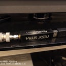
The feedpoint is a panel mount N-Type, however anything could work here providing it is secure enough to take some tension from the wires. To build the director measure out two lengths of wire at least 170mm in length, attach to the feedpoint and pass through the tubing, the remaining wire should then be passed through the opposite tube to form the reflector.
Tie the two ends of each side to a spacer and twist the ends, on the driven element side you should aim to have between 100-150mm of exposed wire at each end, simply cut the reflector down as required but make sure to keep (and wrap) some extra wire so that adjustments can be made. It is critical to provide some tension between all the wires but it should not be enough that it causes the tubes to bend!
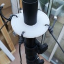
The spacers I have used are made of a soft plastic and measure 34mm in length with the spacing between the holes providing the critical 29mm gap.
*The soft plastic came from a toolbox spacer and was cut using household scissors, alternatives could be tupperware, DVD/CD cases, etc
As mentioned, altering the length of the driven element via minute adjustments at the spacers allowed me to gain an SWR of 1:1.1 across the entire 2M band. One trick I found during adjustment is to twist the reflector wire at its center (inside the junction box) to shorten it more quickly and provide tension.
Step 3: Mounting & Afterthoughts
Any left over tubing can be used to make a stand for the antenna (Don't glue, it'll need to move!), I used some wall clamps and a piece of wood to mount mine in the loft (excuse the mess) and whilst it is horizontal for SSB I plan to add an additional 90' piece to allow for vertical polarisation so that I can access FM stations and repeaters!
The antenna is light enough to be used portable, however I would suggest keeping the boom as long as possible and wiring the antenna via a length of RG58 / Mini-8 coax.
Update 2019: I have been using this antenna in my loft now for a few months and it performs very well with DX of 380Km possible frequently, by all means it does not have the performance of a beam but it also does not have the narrow directionality which as an unmotorised antenna I find more useful.


