

Introduction: Arduino and Floating Data...


Reading serial data, put some calculations on it, it all is so easy with Arduino.
Until... You compare data from one sensor with others. Then you could have strange numbers.
Without a lot of pictures, I'll try to explain some of these, with a simple circuit: measuring temperatures with a LM35C.
Step 1: LM 35: °C From MVolts.
LM 35 is probably the easiest thermometer-chip to use.
One +-line, one ground, one output. According to the data sheet, no need for extra components along the way.
True. If you use a DMM (digital multi meter).
From 0° C to 150°C, every degree the temperature rises, you will measure +10mV more on your DMM. At 20°C, you will measure 200mV (plus or minus a few milliVolts).
So easy, thousands read it from Arduino, so do I.
But then... When you monitor the temperature over the serial connecting with your pc, everything looks pretty ok. Use it with an external power supply, things pretty soon get weird.
It all comes to resolution...
Step 2: Resolutions


Imagine you connect the LM35 to the above pictured analogue meter. You soon find out that it is not that easy to read the temperature.
The best you can tell that, for example, the temperature is somewhere between 20 and 22°C, when you check the scale. So our primary resolution would be "plus-minus 2°C"
Almost... You also have to look out if you are looking straight to the needle. If not, you could be some degrees off.
In the second and third image, you can see more... You have a mirror under the needle. If can't see the reflection of the needle, you look straight at it, that means, you see the right value.
So we can see a little better at our values.
Take the first meter again. If we could multiply our output by two, it means the meter wouldn't go from 0° to 100°, but from 0° to 50°. In that case, when we measure 20°C, the needle would show us around 40, maybe 42. Our resolution would now be "plus-minus 1°C". Thus more accurate.
Let's see now how we can use that with Arduino.
Step 3: Arduino and Temperature.

I found this nice fritzing thing on Google.
The way to connect a LM 35 and an Arduino, pretty straightforward.
Connect the output from the LM to an analogue input, and you can measure.
Measure what?
We know the Arduino has a maximum analogue input of 5V, and the it divides it in 1024 steps. A 10-bit resolution.
So every bit is about 5mV, even a little less. So our resolution would be 0.5°C.
It could easily been written like this:
Temp = analogRead(A0);
float Temp2= (Temp/2);
Where Temp2 would pretty much give us the temperature.
But... We can get a better resolution.
With the use of AnalogReference, we can put the resolution higher, that is, we can get more bits from a reading. In the UNO, we can use "AnalogReference(INTERNAL)", we get 1024 chunks from 0V tot 1.1V. Pretty amazing, doing so will get our resolution, our measuring almost 5times better. Every bit would be about 1mV.
Perfect, unless...
Unless we use more analogue inputs. AnalogReference works on all the analogue inputs at once...
Step 4: Amplify It...


The next problem I stumbled upon, I use a lot of analogue inputs, most go to 5V, so I can't use the AnalogReference.
But I wanted to have some pretty accurate temperature-reading.
So I had to look up an amplifier... Since I studied electronics, things became easier, not that, in my time, I use amplifiers like the one in the picture. Even though I did study them!
It has been ages that I haven't worked with OpAmps, so I needed some online-info. Easy to find, I found this formula for calculating the gain (amplification-factor) of an OpAmp.
Pretty straightforward:See the second image above.
In this, the gain = 1+(Rf/R1).
If you take Rf 47K and R1 4K7, you would have an amplification of 11.
So I made an amplifier, that amplifies exactly 5 times. In stead of having a maximum of 500°C with a normal analogRead function, I would have a maximum of 100°.
The resolution would also be 5 times greater: in stead of about 0.5°C per step, I would have 0.1°C.
Step 5: Temperatures All Over the Range...

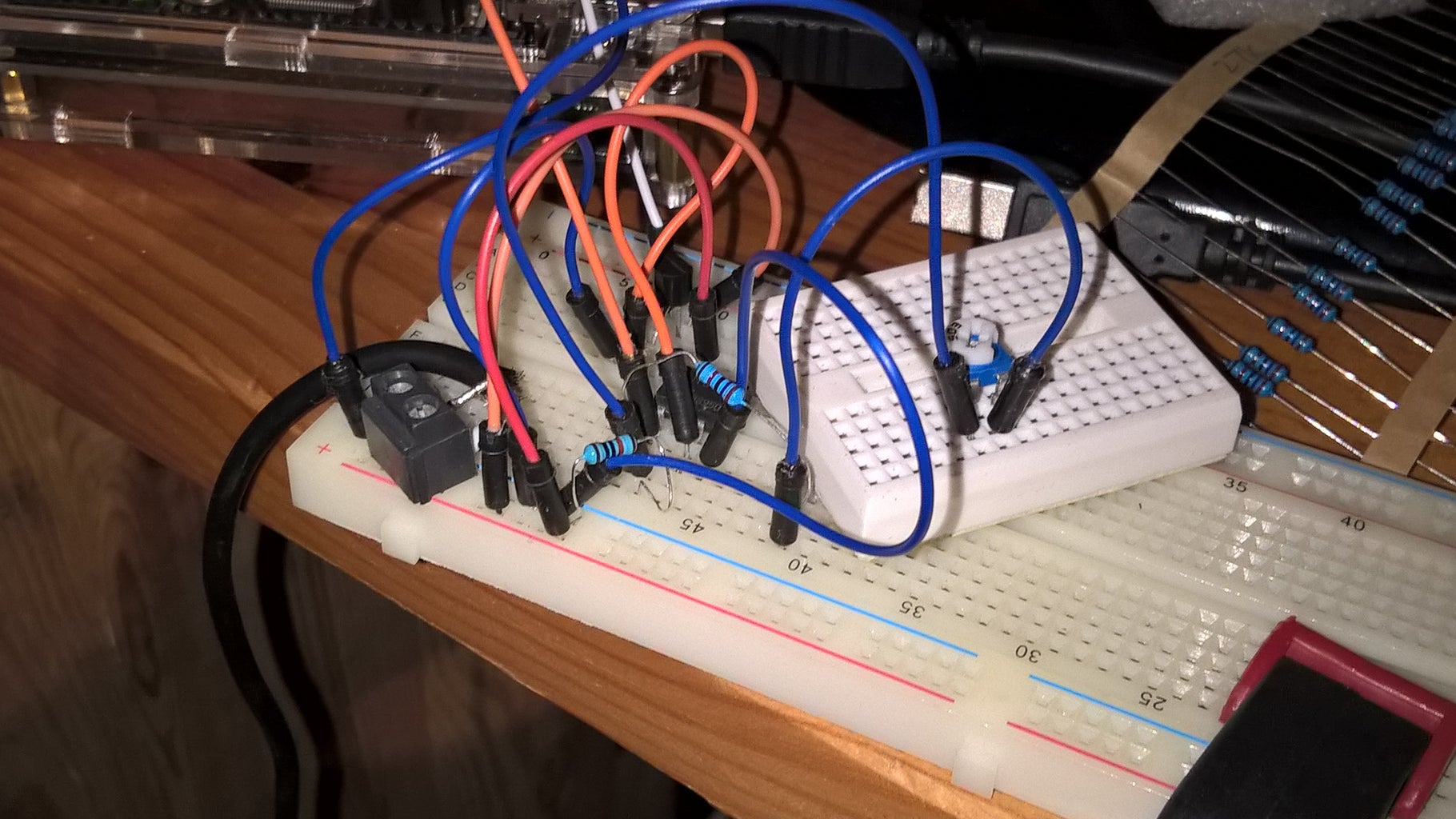
This pretty much works OK. As OpAmp I used a dual 358. You can see that I also use a trimmer, a trim potentiometer. Since I wanted to have the right amplification (X5); I wanted to get the total resistance right. So in this case R2 equals R2 and R3, which can be set.
I measured the input (output of LM35) and the output of the amp, turned the trimmer till I got it right: Input x 5 = output.
And connected it to Arduino.
A0 was the un-amplified output from LM35, A1 was the 5-times greater output from the amp.
Since I already had so weird readings from LM35, I followed them on a serial output.
Disaster...
Compared to a temperature measured by a BMP180...
BMP says 20°C, A0 gave 16.8 A1 18°. A second later, A0 was 18.8°C, A1 19.5... And so on.
in my code I used these two lines:
LM = T * (5000/1024)/10 and AMP = map(T2,0,1024,0,100)
Where LM and AMP are floating data types, T and T2 also, they are the data read through analogRead from the two anlogue inputs.
It took me a while, but I tried the following:
LM = T * (5000.0/1024.0)/10.0 and AMP = map(T2,0.0,1024.0,0.0,100.0)
The temperatures were much more stable!
When the "raw data", the bits gave about 38 to 41 on the non-amplified A0 and 214 to 216 on the amplified input, the calculated results gave from 18.55°C to 21.55°C on the non-amplified input, and from 20.9°C to 21.09°C on the amplified input.
So... It's all about resolution AND making sure your calculations have at least 1 digit behind the decimal point when using float in data types.
Hope you can use some of this instructable, and thank you for reading!
Step 6: Finished...
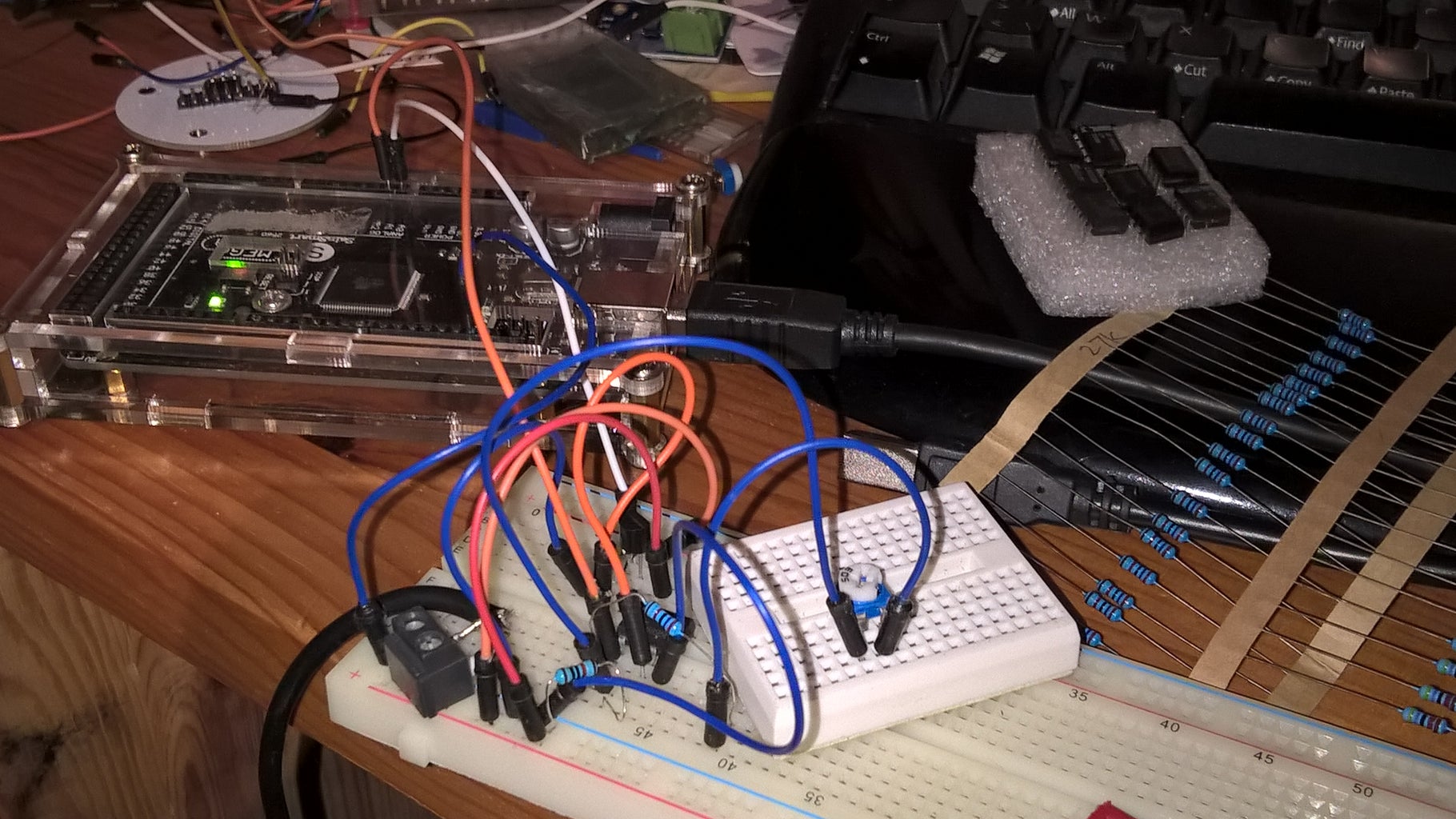
So..; This is pretty how I set up this little experiment.
And, I can still reach my keyboard to type this instructable :-)
I hope you liked it,
Marc.
