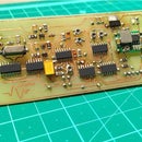
Introduction: DIY Power Measurement Module for Arduino
Hello everyone, I hope you are doing great! In this instructable I am going to show you how I made this Power meter/ Wattmeter module for use with an Arduino board. This power meter can calculate the power consumed by and DC Load. Along with power, this module can also give us accurate readings of voltage and current. It can easily measure low voltages (around 2V) and low currents, as low as 50 mA with an error not more than 20mA. The accuracy depends upon the choice of components based upon your requirements.
Supplies
- IC LM358 dual OP-AMP
- 8 pin IC base
- Shunt resistor(8.6 milliOhms in my case)
- Resistors: 100K, 10K, 2.2K, 1K (1/2watt)
- Capacitors: 3 * 0.1uF ceramic capacitors
- Veroboard or zero board
- Screw terminals
- Soldering iron and solder
- Arduino Uno or any other compatible board
- OLED Display
- Connecting breadbard wires
Step 1: Gathering the Required Components
This project uses very simple and easy to get components: they include resistors, ceramic capacitors, Operational amplifier and a veroboard for prototyping.
The choice and value of components depend upon the type of application and the range of power that you want to measure.
Step 2: The Working Principle.
The working of the power module is based upon two concepts of circuit theory and basic electricity : The voltage divider concept for measurement of the input voltage and the Ohm's Law to calculate the current flowing through the circuit. We are using a shunt resistor to create a very small voltage drop across it. This voltage drop is in proportion to the amount of current flowing through the shunt. This small voltage when amplified by an operational amplifier can be used as an input to a microcontroller which can be programmed to give us the current value.The operational amplifier is used as a non inverting amplifier where the gain is determined by the values of the feedback resistor R2 and R1. Using the non inverting configuration allows us to have a common ground as the measuring reference. For this, the current is being measured on the low side of the circuit. For my application I have chosen a gain of 46 by using 100K and 2.2K resistor as feedback network. The voltage measurement is done by using a voltage divider circuit which divides the input voltage in proportion to the resistor network used.
Both the current value from the OP-Amp and the voltage value from the divider network can be fed into two analog inputs of the arduino so that we can calculate the power consumed by a load.
Step 3: Bringing the Parts Together..
Let us start the construction of our power module by deciding the position of the screw terminals for input and output connection. After marking the appropriate positions, we solder the screw terminals and the shunt resistor in place.
Step 4: Adding the Parts for the Voltage Sense Network
For input voltage sensing I am using a voltage divider network of 10K and 1K. I also added a 0.1 uF capacitor across the 1K resistor to smooth out the voltages.The voltage sense network is soldered near the input terminal
Step 5: Adding the Parts for the Current Sense Network
The current is being measured by calculating and amplifying the voltage drop across the shunt resistor with a predefined gain set by the resistor network. Non inverting amplification mode is used. It is desirable to keep the solder traces small so as to avoid unwanted voltage drop.
Step 6: Completing the Remaining Connections and Finishing the Build..
With the voltage and current sense networks connected and soldered, its time to solder the male header pins and make the necessary connections of power and signal outputs. The module will be powered by the standard operating voltage of 5 volts which we can easily get from an arduino board. The two voltage sense outputs will be connected to the analog inputs of the arduino.
Step 7: Connecting the Module With Arduino
With the module being complete, its now finally time to connect it with an Arduino and get it running. To see the values, I have used an OLED display which used I2C protocol to communicate with the arduino. The parameters displayed on the screen are Voltage, Current and Power.
Step 8: Project Code and Circuit Diagram
I have attached the circuit diagram and code of the power module in this step( Previously I had attached the .ino and .txt file containing the code but some server error caused the code to be inaccessible or unreadable to users, so i wrote the entire code in this step. I know that's not a good way to share the code :( ). Feel free to modify this code according to your requirements. I hope this project was helpful for you. Please share your feedback in the comments. Cheers!
#include<SPI.h >
#include<Wire.h >
#include<Adafruit_GFX.h>
#include< Adafruit_SSD1306.h>
#define OLED_RESET 4 Adafruit_SSD1306 display(OLED_RESET);
float val=0;
float current=0;
float voltage=0;
float power=0;
void setup() {
pinMode(A0,INPUT);
pinMode(A1,INPUT);
display.begin(SSD1306_SWITCHCAPVCC, 0x3C); // initialize with the I2C addr 0x3C (for the 128x32) display.display();
delay(2000);
// Clear the buffer.
display.clearDisplay();
display.setTextSize(1);
display.setCursor(0, 0);
display.setTextColor(WHITE);
Serial.begin(9600); // To see the values on the serial monitor
}
void loop() {
// taking the average for stable readings
for(int i=0;i<20;i++) {
current=current + analogRead(A0);
voltage=voltage + analogRead(A1); }
current=(current/20); current=current * 0.0123 * 5.0; // calibration value,to be changed according to components used
voltage=(voltage/20); voltage=voltage* 0.0508 * 5.0; // calibration value,to be changed according to components used
power= voltage*current;
//printing the values on the serial monitor
Serial.print(voltage);
Serial.print(" ");
Serial.print(current);
Serial.print(" ");
Serial.println(power);
// printing the values on the OLED display
display.setCursor(0, 0);
display.print("Voltage: ");
display.print(voltage);
display.println(" V");
display.setCursor(0, 10);
display.print("Current: ");
display.print(current);
display.println(" A");
display.setCursor(0, 20);
display.print("Power: ");
display.print(power);
display.println(" W");
display.display();
delay(500); // refresh rate set by the delay
display.clearDisplay();
}


