

Introduction: LED Blinking With Arduino Uno R3


Now we can start with a simple experiment to learn the basic operation and code in the Arduino IDE. Before that you should learnt how to install Arduino IDE.
Step 1: Components
- Arduino Uno board * 1
- USB cable * 1
- Resistor (220Ω) * 1
- LED * 1
- Breadboard * 1
- Jumper wires
Step 2: Principle
The operating voltage of the LED is 1.8V and the operating current is 10mA-20mA. The Arduino Uno board can supply 5V or 3.3V power. In this experiment 5V is adopted, so the minimum resistance of the current limiting resistor should be (5 V to 1.8 V)/20 = 160 ohm. The 220ohm offered in the kit is suitable. The larger the resistance is, the lowers the LED will get.
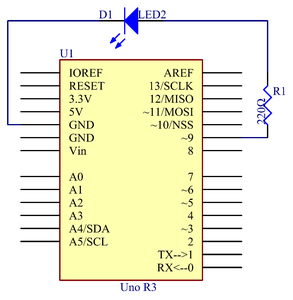
Step 3: The Schematic Diagram
Step 4: Procedures


Connect one end to the anode (the long pin) of the LED to the 220ohm resistor one end, the other end of resistor connected to the Pin 9 in arduino , and the cathode (the short pin) of the LED to GND.
When the pin 9 outputs high level, the current gets through the current limiting resistor to the anode of the LED. And since the cathode of the LED is connected to GND, the LED will light up.
Step 1:
Build the circuit.
Step 2:
Download the code from https://github.com/primerobotics/Arduino
Step 3:
Upload the sketch to the Arduino Uno board
Click the Upload icon to upload the code to the control board.
If "Done uploading" appears at the bottom of the window, it means the sketch has been successfully uploaded.
You should now see the LED blinking.
Step 5: Code
//Blinking_LED//turn on the LED for half a second,then off for half a second,repeatedly
//info@primerobotics.in
//www.primerobotics.in
/************************************************/
const int ledPin = 9;//the number of the LED pin
/************************************************/
void setup()
{
pinMode(ledPin,OUTPUT);//initialize the digital pin as an output
}
/************************************************
/the loop routine runs over and over again forever
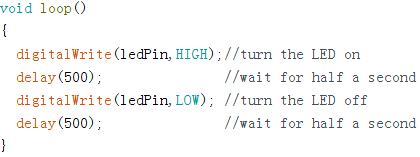
void loop()
{
digitalWrite(ledPin,HIGH);//turn the LED on
delay(500); //wait for half a second
digitalWrite(ledPin,LOW); //turn the LED off
delay(500); //wait for half a second
}
/*************************************************/
Step 6: Code Analysis
Code Analysis 1-1 Define variables
You should define every variable before using in case of making mistakes. In the following code, ledPin stands for pin 9. You can also directly use pin 9 instead.
Code Analysis 1-2 setup() function
A typical Arduino program consists of two subprograms: setup() for initialization and loop() which contains the main body of the program.
The setup() function is usually used to initialize the digital pins and set them as input or output as well as the baud rate of the serial communication.
The loop() function contains what the MCU will run circularly. It will not stop unless something happens like power outages.
The setup() function here sets the ledPin as OUTPUT.
pinMode(Pin): Configures the specified pin to behave either as an input or an output.
The void before the setup means that this function will not return a value. Even when no pins need to be initialized, you still need this function. Otherwise there will be errors in compiling.
You can write:
Code Analysis 1-3 loop function
This program is to set ledPin as HIGH to turn on the LED, with a delay of 500ms. Set ledPin as LOW to turn the LED off and also delay 500ms. The MCU will run this program repeatedly and you will see that the LED brightens for 500ms and then dims for 500ms. This on/off alternation will not stop until the control board runs out of energy.
digitWrite(Pin): Write a HIGH or a LOW value to a digital pin. When this pin has been set as output in pinModel(), its voltage will be set to the corresponding value: 5V (or 3.3V on 3.3V boards) for HIGH, 0V (ground) for LOW.


