Introduction: RGB LED Matrix With an ESP8266
I think these RGB LED Matrix displays are one of best displays you can get for your Arduino projects, they are incredibly bright and vivid and are actually pretty easy to use too!
They can be used for displaying text, images or a combination of both
Check out some of the examples of what can be done with the display:
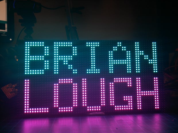
Displaying Text
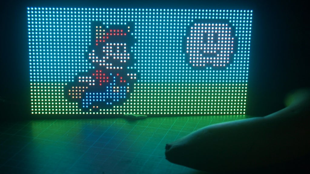
Displaying Images
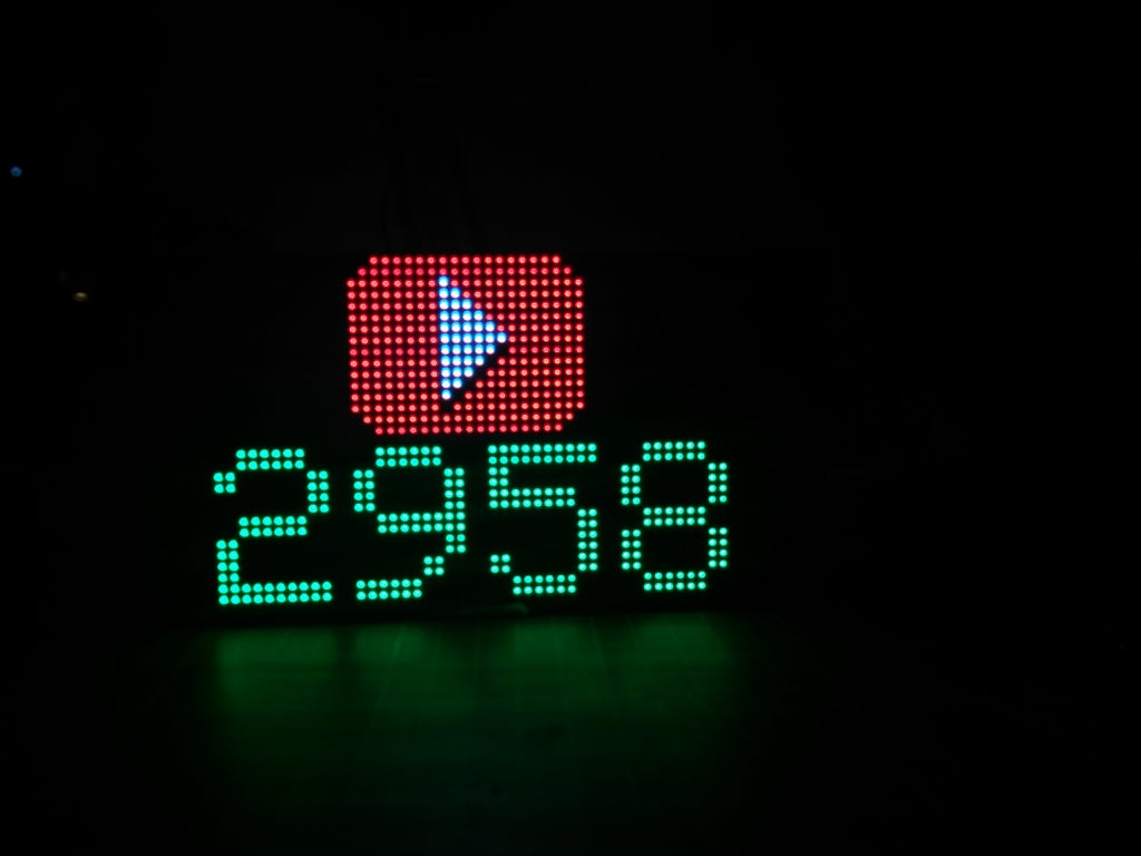
YouTube Subcriber counter
In this Instructable I'll show you how to get started with using these displays with an ESP8266.
Let's jump into it!
Step 1: Check Out the Video!
The video covers the same stuff that's in this instructable if you want to check it out!
Also I have created playlist of any live streams I have done using this display if you wanted to check them out:
Step 2: Different Types of Displays
A good first place to start would be to talk about the different types of these screens available.
The one I have is a P3 64x32 LED Matrix, which reveals two things about the display:
1) The P3 part of the name indicates that the display has a 3mm pitch. This means that between the center of one LED and the center of the next one there is a distance of 3mm
2) The 64x32 indicates how many LEDs there are on the display.
These types of displays come in a lot of different configurations of the above (I think the largest is a 64x64), but they all work pretty similarly.
These displays are actually pretty cheap too! The one I use in this Instructable starts at around $20 delivered. I bought mine off Amazon.co.uk, but all of these should be the same as mine.
Amazon.co.uk* https://amzn.to/2HyLRbD
Amazon.com* https://amzn.to/2KmsJvl
Aliexpress* http://s.click.aliexpress.com/e/EMvjy3z
*= Affiliate Links
Step 3: What Do We Need to Use the Display
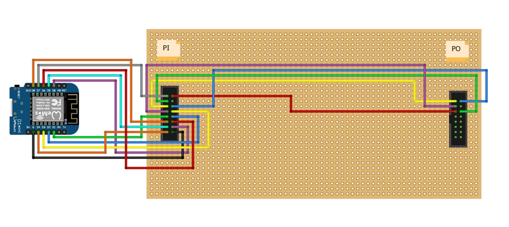
EDIT: Since making this guide, I have made a PCB that makes using these displays really easy! It makes use of the wires than come with the displays for easier connections.
If you are interested in buying one, I sell them on my tindie store.
If you are based in the UK, Colin Hickey also sells them on his store
If you get the board all you need to get is an Wemos D1 mini style ESP8266 and a Power Supply (both listed below)
Along with the actual display you will also get the following:
- A ribbon cable - this can be used to chain displays together (which is supported by the library we will be using, but I only have one display so I won't be able to advise on it)
- 4 screw mounts - these screw into the back of the display and have magnets on the bottom of them so you could attach this display to something metal
- Power connecting cable - This cable connects to the power connection of the display and exposes two terminals for you to power it with (more about this in the next step)
Power Supply
The first thing we'll need is a pretty large 5v power supply, Adafruit suggest that 64x32 matrix can require up the 8 Amps! This is worst case scenario (all LEDs set to white) so in reality you probably won't need one that big, but there is no harm in having the head room. There are two different types of power supplies that you can get:
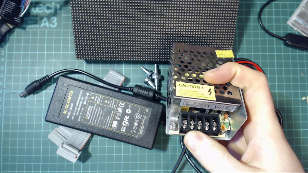
Types of PSUs - Laptop style on the left
One is similar to a laptop and has a 2.1mm jack as its output and there other is more similar to type that comes with 3d printers.
I much prefer the laptop style as the other requires you to connect mains voltage wires to it, and working with mains voltage is something I like to avoid as often as possible! Here is a link to the same type of one I used (5v 8 amp laptop style)
Amazon.co.uk* https://amzn.to/2JBauB2
Amazon.com* https://amzn.to/2Ko5WiX (This seems to come with the adapter for connecting to the power cables)
Aliexpress* http://s.click.aliexpress.com/e/vzJ2rnE
Other Components
The only other things we need are
- An ESP8266 development board, I recommend the Wemos D1 Mini Clone* as they are very small and cheap ($3 delivered).
- Female to Female 20CM Dupont cables*
- 10pcs 2.1mm Adapters*, This contains a set of both sockets and plugs, but they are pretty cheap and useful so worth picking them up.
Step 4: Software Setup
There are a couple of things you will need to have setup before you can start using these displays.
Installing Arduino IDE & ESP8266
If you have never used the ESP8266 or Arduino before, we will need to a little bit of software setup. I have a dedicated video for this. It's only 5 minutes long and goes through everything you need to setup.
If videos are not really your thing, check out lesson 2 of Becky's awesome IoT Class, it goes over everything you need as well.
Before you move to the next section you should be able to upload a simple sketch to your ESP8266 (such as the blink example mentioned in both the video and Becky's lesson)
Installing libraries
To use the display we are also going to need to install some libraries.
The first one we need to install is the PXMatrix Library by 2Dom. It is in the process of being released to the library manager but at the time of writing this Instructable the library is only available through Github. Try search for "pxmatrix" inside the library manager (Sketch -> Include Library -> Manage Libraries), but you might need to just download the zip file from Github and add to Arduino IDE that way. (Sketch -> Include Library -> Add .ZIP Library)
We also need to install the Adafruit GFX library. To install this you can search for it on the Arduino library manager.
Step 5: Wiring It Up
Connecting Up The Power Supply
First thing we need to do is connect the power supply up to the wires that came with the display.
The Adafruit learn guide recommends connecting up the wires like this:
I couldn't get this to make a solid connection (physically), but who am I to question what Adafruit suggest! If you do go down this route make sure to use some insulating tape or heatskrink to give it some strength.
I ended up using a couple of screw terminals and piece of perfboard to make a small board for connecting the power supply to the wires, I was happy with how it turned out!

Connecting Up The Data Wires
Next we'll hook up the the data wires for the display. The library github lists a couple of different pin layout examples, but only the labels seem to change between the different ones and mine didn't have any labels at all! I wired the board as follows:
You'll notice on the back of the display that there are two connectors, the one you want to wire to is the one where the arrows are moving away from it

Some of the pins are not needed depending on what display you have, these are the C, D and E pins. The library lists instructions for when you need to connect up these pins based on the scan rate of your display:
| Display Pin | ESP8266 Pin | Note |
|---|---|---|
| C | 15 (D8) | Only for 1/8, 1/16, 1/32 scan |
| D | 12 (D6) | Only for 1/16, 1/32 scan |
| E | 0 (D3) | Only for 1/32 scan |
Although my display is a 1/16 display and I needed to for E connected up. This is what it looked like without it:

The best way to check if they are required for your display is they seem to be connected to ground on displays where they are not needed. Get your multimeter in continuity mode and check these pins against the ground pin, if the pin is connected to ground you don't need it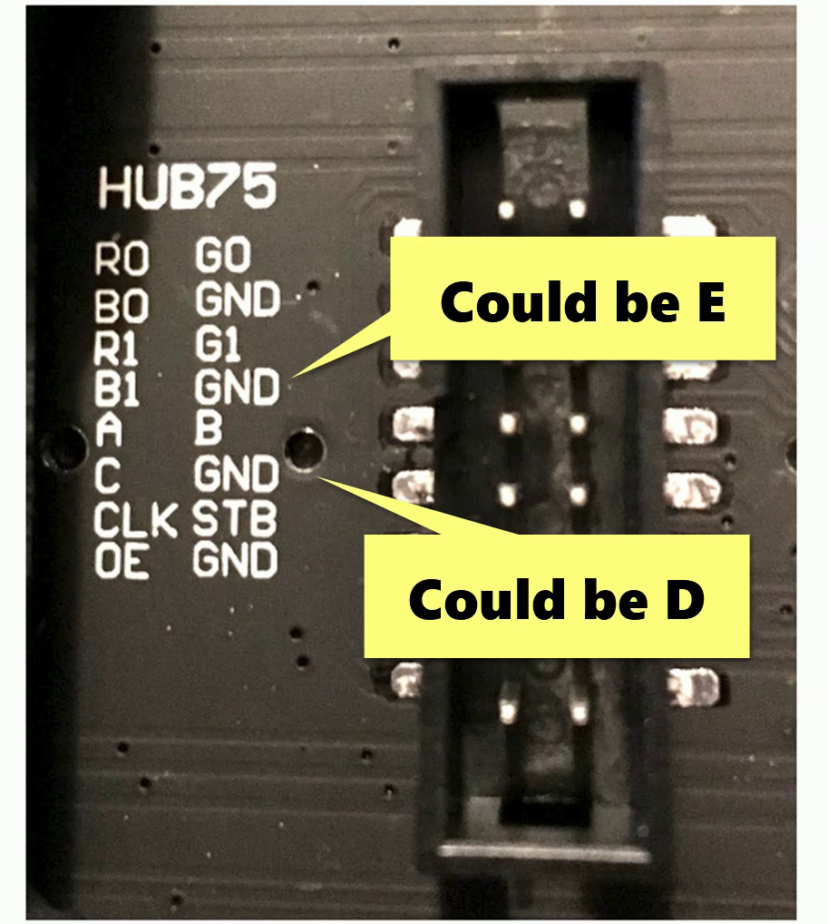
Some Wiring Notes
It is also possible to power the ESP8266 off the same power supply as the display, but the simplest and safest way is to power them separately.
If you do want to power off the same supply, on the Wemos D1 mini board we can connect the 5v of the display power supply directly to the 5v pin. Two things to be careful about:
- If you plug in just the USB and not the larger power supply then display will try run off the USB power and it could cause overload your USB supply. You could fix this by putting a diode between the display power supply and 5v pin (so current can only flow towards the esp8266)
- If you are not using an Wemos D1 mini make sure whatever pin you are connecting to has a voltage regulator connected to it (Don't connect directly to the 3.3v pin!)

One other note. If you are using a ESP8266 that doesn't use pins labeled with a "D" in front of it (e.g. D1, D2 etc) you can use the following Diagram to map the pins to the ESP pins. For Example D1 is connected to GPIO pin 5, so if your board uses the GPIO pin numbers connect that connection to 5.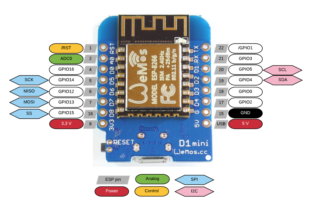
Step 6: Using the Display
We are now ready to start using the display. First we are going to use on the examples from the library to test everything is working ok.
In your Arduino IDE, go to File -> Examples -> Px Matrix and open the pixeltime example.
The first thing we need to update is the configuration for what type of display we have. The following default configurations are in the example:
PxMATRIX display(32,16,P_LAT, P_OE,P_A,P_B,P_C);
//PxMATRIX display(64,32,P_LAT, P_OE,P_A,P_B,P_C,P_D);
//PxMATRIX display(64,64,P_LAT, P_OE,P_A,P_B,P_C,P_D,P_E);
Enable the one that matches your display based on what pins are needed (as described in the previous step), mine had the C, D and E pins so I would remove comment from the last one and comment out the rest.
Next we want to set the resolution of the display, this is the two numbers at the start. Taking the "32,16" one as an example, 32 is the amount of pixels wide it is and 16 is the amount of pixels tall it is. Change this to match the display you have. Mine was 64 x 32 display so my configuration ended up like this:
PxMATRIX display(64,32,P_LAT, P_OE,P_A,P_B,P_C,P_D,P_E);
Next we want to set the scan rate of our device, this is normally found on the product listing of where you bought the display. Mine was a 1/16 display
In the setup of the example you will see the following line:
display.begin(8);
This indicates that display is a 1/8 scan display, so change this line to whatever your display is. Mine would be display.begin(16)
That is all the code changes required, one last configuration change that the author of the library recomends is to set your CPU Frequency of your ESP8266 to 160MHz, this will make your ESP8266 run faster which will improve how the display works. You can do this easily in the Arduino IDE, go to Tools -> CPU Frequency and set it to 160MHz.
You can now upload the example sketch to the board.
The example is quite good and shows off couple of different features available when using the display, such as writing text, drawing shapes and displaying images
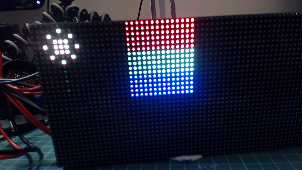
PixelTime example
Step 7: More Examples
Just as a bit of fun I decided I'd add a couple more examples of things you can do with the display.
The first couple of examples are displaying an image on the screen. One example is a picture of Mario and the other is the instructables robot. Code for these examples can be found here:
https://github.com/witnessmenow/LED-Matrix-Display...
Both of these were drawn up in paint.net (setting the image size to be how many pixels I wanted, e.g. 64 x 32) and then converting the image using this converter: http://www.rinkydinkelectronics.com/t_imageconvert...
The last example is a more dynamic one, it uses my YouTube API library to display your live YouTube subscriber count on screen. Code for this example can be found here:
https://github.com/witnessmenow/LED-Matrix-YouTube...
Hopefully you found this instructables useful. As mentioned at the start I think this is one of the most impressive displays available for an Arduino project at the moment. As always if you have any questions I would be happy to try help!
If you want to see more stuff from me:
Videos: Check out my YouTube channel for more Videos
Live Streams: I live stream working on electronics projects every Monday on Twitch
And I talk electronics and other random stuff on twitter - @witnessmenow
All the best!
Brian


