Introduction: Telepresence Robot: Edge Detection
In the last instructable we learned how to navigate around obstacles directly in the robot's path. However, we didn't answer the fateful question of what to do if the path ends. In its current configuration, if the robot encounters a sudden drop such as a table ledge, staircase, or cliff, it will just fall to it's doom. With this in mind, we are going to build a homebrewed edge detection sensor to solve this problem.
The edge detection sensor uses two LEDs and a photocell ambient light detector (a.k.a. an LDR, CdS Cell or photoresistor) to determine if there is a drop. It works by shining an LED at the surface below the robot and measuring the amount of light that is reflected back to the sensor. When there is a sudden drop, no light gets reflected back and the robot knows to stop moving forwards, back up, and then change course. This is a simple, yet effective way to keep the robot from falling to its doom.
This is the fourth part of a seven-part instructables series. Over the next two instructables we will be building the basic electromechanical robot platform. This platform will later be enhanced with sensors and additional control electronics.
To learn more about the topics covered in this series of projects check out the Robot Class, Electronics Class, and Arduino Class.
Step 1: Materials
Step 2: Build the Circuit
Prepare yourself mentally. This is probably the trickiest single circuit we will be building in this class.

There are two parts to this sensor. The first is the LEDs, which get connected in parallel to a digital output pin so the Arduino can turn them on and off. The reason for this is that the Arduino will actually be taking two light reading measurements. The first measurement it will take is with the LEDs on and the second is with the LEDs off. In order to do this, we obviously need to be able to toggle the LEDs.
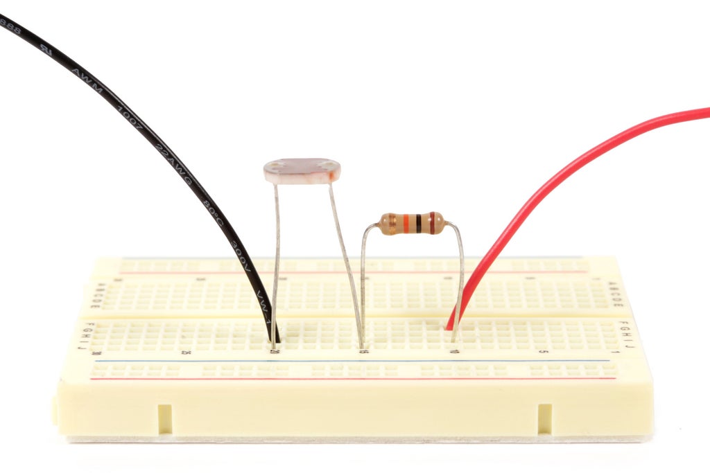
The second part of the sensor is the photocell which gets connected to an analog input pin. The photocell is a resistive sensor, meaning that the resistance changes depending on how much light hits it. We are going to use the Arduino analog pin to measure a change in voltage when the sensor is in use.

However, the sensor is resistive and by itself, will not change the amount of voltage reaching the pin. To do this we need to create a special arrangement of components called a voltage divider. A voltage divider is basically two resistors in series between power and ground. The midpoint between the two resistors is a voltage that ranges between the highest voltage in the circuit (5V in our case) and ground. This voltage is determined by the ratio between the two resistors.

If we replace one of the resistors with a photocell (or photoresistor), the voltage at the midpoint of these two resistors will fluctuate depending on how much light is at the sensor. If we then connect this midpoint to an Arduino analog pin, we can take a reading of the voltage present. In doing this, we have converted the fluctuations in the resistive sensor to changing voltage that an Arduino can read.
When the Arduino reads the voltage, it then returns a number between 0 and 1023. These value correspond to a voltage between 5v and ground, where 0 is ground and 1023 is 5V. To convert the Arduino reading to a voltage and display it in the Serial Monitor, you would add the following lines to the Main loop of the demo code:
int sensorValue = analogRead(A0);
float voltage= sensorValue * (5.0 / 1023.0);
Serial.println(voltage);

Anyhow, now that you understand better what is going on, build the circuit as pictured in the wiring diagram on a breadboard. While you can probably put the LEDs just about anywhere near the photocell, you will undoubtedly get the best results if you place one on each side of the photocell. Simply connect the corresponding pins of the LED together with wire to attach them in parallel (i.e. connect the two long power leads together, and the two short ground leads together).

Upload the following code to test it out:
Step 3: Build the PCB
Once it is working on a breadboard, the next step is to build the circuit on a PCB (typically printed circuit board, but or in our case, prototype circuit board). To do this, we are going to solder the components to the board according to the connections in the wiring diagram.
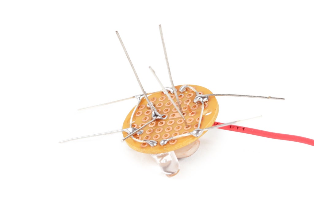
Some PCBs have long metal bus traces on them similar to breadboards. However, the one we are using does not. It just has lots of individual unconnected solder pads. As such, we're going to free form the connection on the underside of the PCB. What this means is that instead of connecting the components through metal bus lines, we are going to literally make each connection by soldering the component leads together. If a connection is to be made, the leads must touch and be soldered.


To start, insert the LEDs, bend the leads outward to hold them in place and then solder them to the circuit pads where they have been inserts.


Next, insert the resistors. Again, bend the leads and solder them to the solder pads.


From here, we want to bend the ground leads of the LEDs such that they intersect with one of the leads of the 10K resistor. Make sure they are not touching any other component and solder them together.


Next, repeat this with the power leads of the LEDs and one of the leads of the 100 ohm resistor. Solder these together as well.


Finally, insert the photocell such that the surface of the sensor is aligned with the top of the LEDs. Solder both of the photocell leads to their corresponding solder pads. Then, attach one of the photocell leads to remaining lead of the 10K resistor.
Step 4: Attach Wires
Once all of the connections between components are made, the last step is to connect the wires.


To start, connect a 12" solid core red wire to the last remaining lead from the photocell.

Then, solder a 12" solid core green wire to the junction between the photocell and the 10K resistor.

Connect a 12" solid core black wire to the LED ground leads.

Finally, connect a 12" solid core wire of color of choice (I used orange) to the 100 ohm resistor connected to the LED power leads.


Trim away all the excess leads until it is nice and clean looking. Examine carefully to make sure none of the connections have accidentally crossed. Once sure nothing is touching that shouldn't be, you're done.
The circuit board should now theoretically be complete. You have just made a an edge detection sensor.
Step 5: Shrink Tube
The sensor works better if you put a little bit of shrink tube around the side of the sensor. This blocks any ambient light from reaching the sensor and makes it more accurate.
Simply slide the shrink tube around the photocell, and quickly heat it up, so that it loosely locks into place.
Step 6: Plug It In
If need be, loosen the nut firmly locking the CD in place. Then, open the box lid to access the Arduino.

Pass the black, green and orange wires up through the holes in the bottom of the lid.
Don't worry about the red wire. The red wire from the sensor will get soldered to the red wire connecting the switches.

Plug the wires into the Arduino in as follows:
Black - Ground
Green - Analog Pin 0
Orange - Digital Pin 3


Finally, solder the red wire to the junction between the switches power wire and 10K resistor. This is essentially connecting the edge sensor to 5V power. Unfortunately the Arduino only has one 5V power socket, so we will have to make the connection this way. It is not pretty, but it is effective.
Step 7: Program the Arduino
Program the Arduino with the following code:
What this code is doing is taking a voltage reading with the LEDs on and then another with the LEDs off. It is then comparing the difference between the two readings. When it is on a table top, a lot of light gets reflected back when the LEDs are on, making the difference between the two values rather high. When there is a large difference like this, we can assume it is safe to keep driving.
However, when the sensor is over a sudden drop into the abyss, no light gets reflected back. In this case, the sensor returns close to the same reading to the Arduino whether the LEDs are on or off. When the difference between the two values is low, we know that we have found a drop. The Arduino can use this information to tell the motors to stop driving, back up, and change course.
Step 8: Attach the PCB
Firmly close the case back up and fasten the CD back in place.
Cut free one of the zip ties holding the switch in place. Thread a new zip tie back through the switch and one of the mounting holes on the edge detection sensor.
Repeat the process for the second switch.
The sensor PCB should now be securely attached to the underside of the CD.
Step 9: Adjust the Sensor (optional)
If your robot is anything like mine, then the CD is bent forward and the sensor is nearly dragging on the ground. While this won't affect the way the sensor is operating, it is probably not the greatest idea.
Fortunately, this can be fixed with a zip tie or two. I simply threaded one through the latch for the lid and pulled it just tight enough to bend the CD upwards slightly. Problem solved.
If you don't have a latch, you can drill a hole or two in the lid and thread the zip tie through - or something. Building robots is all about being willing to improvise and solve problems. Don't be afraid to experiment.
Step 10: Carefully Test It Out
Put in batteries to test it out. You are probably wondering why we haven't added a power switch. Well... I forgot...
If this is really annoying you, learn how to add a power switch by skipping ahead to step 1 of the final lesson.
Anyhow...
Go find a ledge and try it out.
However, you will likely want to be there to catch it should it not work right the first time.


