Introduction: Ultrasonic Sensor & Servo: Reactive Motion With Arduino


First you need to gather relevant materials to put this circuit together.
Supplies
1 Arduino
1 Ultrasonic Sensor HC-SR04
1 Servo
1 Breadboard
3 Black Jumper Wires (Ground/Negative)
3 Red Jumper Wires (Voltage/Positive)
3 Color Jumper Wires (Input/Output)
Step 1: Understanding the Components


It is important before putting together the physical circuit to understand each component:
The breadboard has two sets of power rails on either side, that have slots for negative (black/blue) and positive (red) inputs. They are connected in series vertically. Terminal strips share the connection horizontally, however parallel terminal strips will require a jumper wire to bridge the divider.
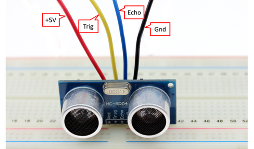
The ultrasonic sensor has a VCC/5V pin (red), a Trig pin (color), an Echo Pin (color) and Ground/GND pin (black). The link explains how PWM works in relation to the sensor.
The servo has a 5V port (red), a Pulse Width Modulation/PWM port (color) and a Ground/GND port (black). Click the link to know more about how it works.
Step 2: Setting Up the Circuit
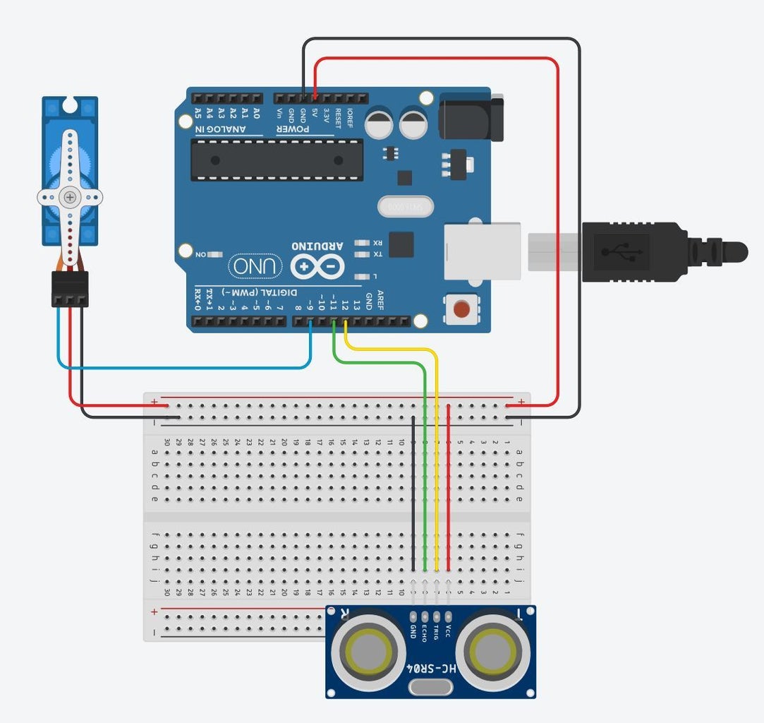
Follow the diagram layout. While setting up the circuit, always remember to keep the arduino unplugged to avoid any damage to your components.
Plug the ultrasonic sensor into the breadboard, taking note of its orientation (this will be important when using the jumper wires to connect to the arduino). Connect VCC with a red jumper wire into breadboard's positive power rail. Connect GND with a black jumper wire into the breadboard's negative power rail. Connect Trig with a color jumper wire into Digital PWM port 12. Connect Echo with a color jumper wire into Digital PWM port 11.
Plug the servo into to the breadboard and arduino. Use a color jumper wire to connect it's input/signal port to the digital PWM port, 9 on the arduino. Plug the red jumper wire into positive power rail and a black jumper wire into GND power rail.
Step 3: Download Arduino GUI and Input Code
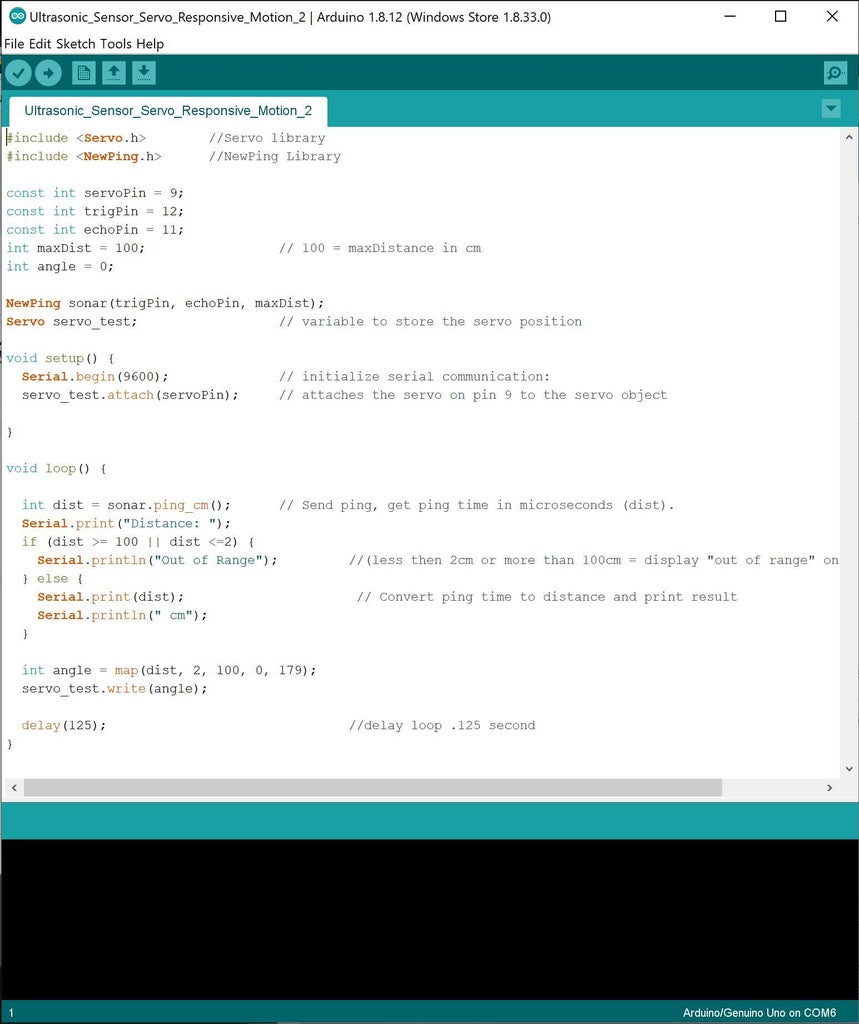

Download Arduino Graphical User Interface (GUI) here.
Plug in the code below, note the information to the right of "//" tells you what that line of code is doing:
----copy below and paste into arduino GUI----
#include <Servo.h> //Servo library
#include //NewPing Library
const int servoPin = 9;
const int trigPin = 12;
const int echoPin = 11;
int maxDist = 100; // 100 = maxDistance in cm
int angle = 0;
NewPing sonar(trigPin, echoPin, maxDist);
Servo servo_test; // variable to store the servo position
void setup() {
Serial.begin(9600); // initialize serial communication:
servo_test.attach(servoPin); // attaches the servo on pin 9 to the servo object
}
void loop() {
int dist = sonar.ping_cm(); // Send ping, get ping time in microseconds (dist).
Serial.print("Distance: ");
if (dist >= 100 || dist <=2) {
Serial.println("Out of Range"); //(less then 2cm or more than 100cm = display "out of range" on serial monitor
} else {
Serial.print(dist); // Convert ping time to distance and print result
Serial.println(" cm");
}
int angle = map(dist, 2, 100, 0, 179);
servo_test.write(angle);
delay(125); //delay loop .125 second, changing this makes the "loop" faster
}
Step 4: Ultrasonic Sensor + Servo + Arduino
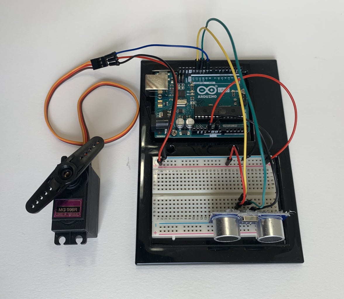
This is how the final circuit should look. Watch the video to see how it works.