Introduction: A Linear Laser Brush for Painting With Light
If you love photography and experimenting with special effects you will be happy to know that with a very simple circuit and a cheap laser you can easily build a sort of laser "scanner" to take impressive photos and portrait.
My project was born from a more complex automated laser scanner idea, and I decided to build this cool gadget so that you can give vent to your creativity.
My project was born from a more complex automated laser scanner idea, and I decided to build this cool gadget so that you can give vent to your creativity.
Step 1: Laser and Instructions
This is a very common laser but its head projects a line, not a dot. You can easily find a red laser line on ebay.
I thought that if I was able to generate a pulse on that laser and I could set the frequency at my choice, the persistence of vision of photographic techniques should let me create many beautiful effects. Just turn flashing on and move your laser beam during the long exposure of the photo.
I thought that if I was able to generate a pulse on that laser and I could set the frequency at my choice, the persistence of vision of photographic techniques should let me create many beautiful effects. Just turn flashing on and move your laser beam during the long exposure of the photo.
Step 2: The Pulse Circuit

You will notice that changing the values of components (on the falstad window right click on components and choose "edit") the frequency and duty cycle change.
Step 3: The Full Schematic
Now I only need to add the power source for the laser diode, a switch and some capacitors as circuit protection.
I know that laser consumes 5 mW and it requires +5V DC, so as power source I used a 78L05 voltage regulator (which provides 5V at 100 mA max). The NE555 controls the laser through the PNP transistor (you can use 2N3906, PN2907, BC556, BC557, BC559, 2N2907...), which also is needed to reverse the output signal, so that the short pulse of the wavelength stays up.
Step 4: The Pcb
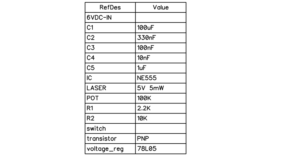
For now I decided to build only a prototype, but I also created a fast pcb if you wish to etch your own circuit. I used DipTrace which is a very simple software. It also develops a bill of materials, from which you can see the reference names and values for each component. C1 e C5 are electrolytic capacitors, the other three (smaller values) are ceramics with no polarity.


In the attached pdf you will find a board schematic ready for toner transfer method (top view). Look at my other instructables if you wish to learn how to etch your own pcb.
Attachments
Step 5: The Prototype
Building a prototype was in this case essential, because I wanted to experiment different frequencies and take some test picture.
So I inserted all the components on a little breadboard and I connected a battery pack, composed by 4 rechargeable 1.2V AA batteries. Actually this could be a bit weak, because the resulting 4.8V is less than 6V required, anyway it works well. I still have to test it with 4 alkaline 1.5V batteries.
So I inserted all the components on a little breadboard and I connected a battery pack, composed by 4 rechargeable 1.2V AA batteries. Actually this could be a bit weak, because the resulting 4.8V is less than 6V required, anyway it works well. I still have to test it with 4 alkaline 1.5V batteries.
Step 6: Test Pictures
Finally I could take some test photos. To obtain the best result turn off any other light source so that it's almost completely dark, then set your camera to 800 ISO and full aperture width, choose the best shutter time depending on what you want to "paint" and... that's it!
As you can see the only limit now is your imagination ;-) I still have to try to shoot some portraits.
As you can see the only limit now is your imagination ;-) I still have to try to shoot some portraits.


