

Introduction: 3D Printed Wi-Fi Clock With Real Time


Hey there welcome again to my new instructable, In this project, I will show you how I made this 3d printed wifi clock that is an amazing companion while you work that shows the real-time, date, and day.
Since most of the household clocks are analog they start to show incorrect time as time passes by, This simple issue can be solved by using these real-time clocks.
Now you may wonder why use this clock, the answer is simple since it is connected to the internet the time is obtained from the ntp server and that is considered as one of the most accurate time sources for IoT devices.
The device is powered by a rechargeable battery and has a good backup time and will sit on your desktop during your productive hours and also adds aesthetic to the place.
If you are building this project i have given all the sources and still if you have any questions ask in the comments after watching video in the end.
Supplies


The supplies used to build this project is available easily and i will give purchase links too
Nodemcu
Jumper wires
LCD display matrix module
Small breadboard
USB charging module
Lithium-ion battery and holder
3D printer
Slicer
USB cable
Step 1: 3D Design


I have designed the parts for this project using the Tinkercad application, It's a web-based application and I would recommend checking this out since it is very handy for 3d designing such things.
I have made several trials and errors to come up with a final design and since you don't need to design this from the very beginning I have given the files below
All you have to do is download the file and use it one any slicer software and save the 3d files on an SD card.
This SD card is later fed to a 3d printer and now we can start to print these parts.


Step 2: 3D Printing


There are 3 parts in total and i printed body as a whole while the side slots were printed together.
I will be using PLA filament to print the parts and the color of the filament is left to you, in my case color combinations like yellow and red or white and black would do the job.
After the print process is over if you have any minor surface issues clean it with emery paper, in my case everything was fine.
This completes the casing or covering part for the clock now let us head over to the electronics and program part for this clock.
Step 3: Circuit Diagram and Program


Before building the circuit upload the program to the nodemcu board, all you have to do is copy and paste the below program on IDE
Replace the wifi id and logins with yours, select the proper type of board and hit on that upload button, After the code is done uploading we can disconnect the USB and carry on with the next steps..
There are 2 files with .h names create a folder inside your ide and paste the code and save and upload.
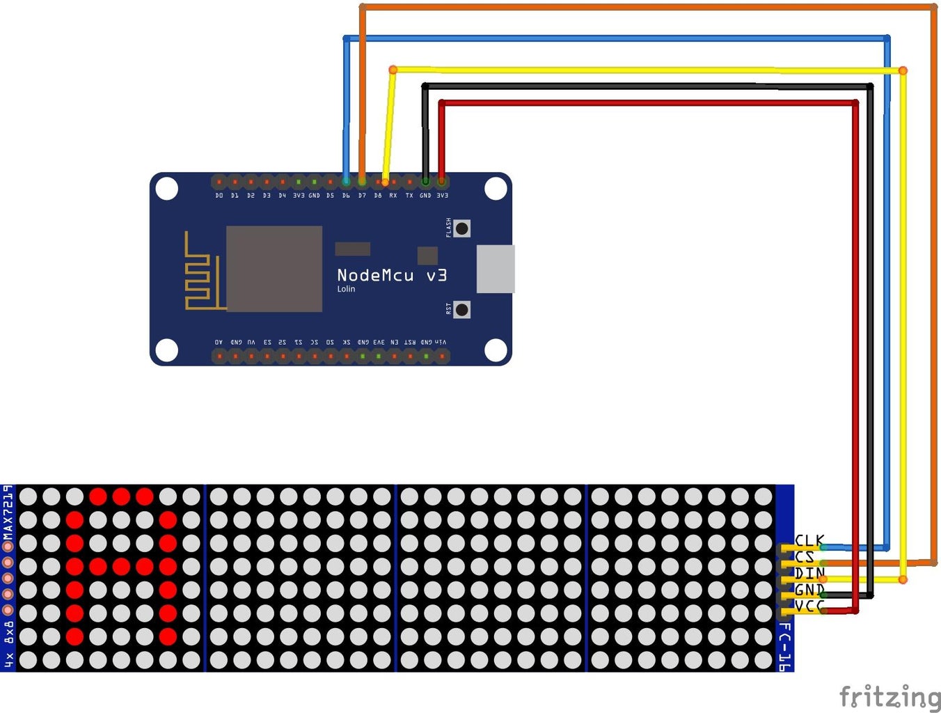
The circuit diagram is very straightforward here, We have only one component that needs to be connected to the nodemcu board.
The LCD matrix display has 4 pins, Clk, Cs, Din, Gnd and Vcc
Gnd and Vcc are connected to the ground and 3v pins of the nodemcu board.
Clk to D6
Cs to D7
Din to D8
After these connections are complete using the jumper wires we can test the project, all you have to do is connect the nodemcu board to the USB power supply, In my case i connected this to the computer.

Step 4: Testing


Before casing all the electronics inside the case make sure to connect all the component and check if everything is fine.
This is because in case if anything does not work after we have done all the placing inside the 3d printed case it adds another level of complexity to dismantle again.
Simply sort this issue by connecting the electronics together, after everything looks fine couple all the 3d printed parts.
Use hot glue wherever necessary and ensure there are no hanging parts, Since this is now complete we can head over to test this project.
You also can simplify this circuit with a Simple small PCB, Complete your electronic projects in the best way from PCBWay
Why them? They have provided me with the best PCB and The quality is just amazing compared to other providers in the market, They also have Color PCB printing Try it out.
Don't have a 3d printer? You can get the best 3d printing service here
Check Here for Rigid-flex Pcbs with this your circuit becomes flexible! I have added the images to this step kindly check.
A revolutionary solution that combines the best of both rigid and flexible circuitry to elevate your electronic projects to new heights.
With their expertise in advanced manufacturing techniques, they offer a seamless integration of rigid and flexible components, ensuring enhanced reliability, durability, and space-saving benefits
Step 5: Testing


There is nothing much in this step, If your battery is low on charge keep the battery for charging usually it takes 2 hours for a full charge, and disconnect the cable from the charging port.
Now connect the cable to the nodemcu board, You will now see a connecting message on the matrix display.
Wait for 10 seconds and the board will automatically be connected to Wi-Fi and it will start to show the time followed by a sliding animation of the day and month.
The things are fully customizable and you can alter them as per your taste.
That is all for now, if you have any suggestions we can discuss that over in the comments, Thanks, and have a good day.
Step 6: Working Video
Few things are better with a video! I'm just kidding here if you watch my video that shows the working of this project along with a complete end to end project making process you will find this project even more interesting.
The animation on this clock looks very good and you should not miss that out.
If you still have any questions about this project ask in the comments and i will be happy to answer, Thanks and happy making.

This is an entry in the
Making Time Contest


![Tim's Mechanical Spider Leg [LU9685-20CU]](https://content.instructables.com/FFB/5R4I/LVKZ6G6R/FFB5R4ILVKZ6G6R.png?auto=webp&crop=1.2%3A1&frame=1&width=306)


