

Introduction: 3D-printable "Garden" Flag Rod


Garden flags often are used for decor indoors but finding one that is the perfect fit for a really good price can be quite annoying. Luckily, any tinker-er out there with access to a 3D printer can easily create their own for next to zero cost. In this instructable I will walk you through the simple steps it takes to model one in Fusion 360 even if you have zero experience with CAD design!
Requirements:
A copy of Fusion 360
A 3D Printer (if you would actually like to print it)
Step 1: Create a New Design/Component


Start up Fusion360, head up to the file button, and click on new design.
There a few different ways to go about creating multiple part designs in Fusion360 but the method I prefer is to use the component feature.
In the browser on the left side, left click on the top rectangle which has the name of your design. Click on "new component" in the menu that pops up. "Component1" should appear as a new rectangle under the others with a color on the left side. You can rename it by a slow double click.
Step 2: Create the First Sketch


At this point we get to start the fun of sketching things but first make sure that the component we are working on is active. To do this, go to the browser window and make sure that there is a eye-looking dot on the right side of the component name. If not, right click on the component and click "activate".
Now go to the top left above the browser and click the new sketch icon directly left of where it says "model". It will ask you to select a plane which in this case doesn't really matter so I just picked the X plane.
In this tutorial we are going to end up using the Revolve command which takes a sketch and wraps it around a centerline.
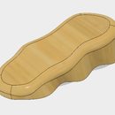
Go up to where you clicked new sketch and click under the icon where it will drop down a menu. This is your sketch palette. Using Lines and circles, draw out a long rectangle with a few jagged points on the top of one side (depending on how you want your design). It is easiest if you keep the bottom line parallel to the x plane/running through the centerline so that you may use that to revolve later on.
Use the "sketch dimension" option under the sketch menu (or press D) and click on any line to create the measurements that you'd like. Remember that this is being revolved along the bottom edge so you'll want to halve whatever diameter you had intended it to be and use that as the height.
Use the "fillet" tool on the sharp jagged upward points to give the sketch a more curved look.
Make sure the sketch endpoints are fully connected the whole way around and it shows up yellow on the inside.
Step 3: Revolve

Once the sketch is complete we can use the revolve tool. It is located in the menu under Create (next to sketch) in the tool bar.
It will ask you for a profile so click anywhere in the yellow part of the sketch that you just created.
Next it asks for an axis. Here is where keeping the sketch level on the centerline helps. You can go over to the browser column and click the arrow on the left side of origin to expand it. There you have the option to click an axis so click on the x axis.
You should see the sketch revolve and turn into a blue 3D shape. Click okay and it completes the process.
If you don't like how the end turned out you can go down to the bottom of the screen and right click on the white box with a pencil (this is the sketch icon) and click edit sketch. Change up your design and hit ok and it will be updated. You may have to play around with this a few times until you get something you like.
Step 4: Hanging Hole Sketch

Now that you have a revolved side, let's put a hole in it so that a string can be placed through it.
Hit the create a sketch button and click on the X plane (or whichever plane you clicked in the very beginning). You'll want to center the hole on the body so start by drawing a line lengthwise down along the center of it. The component should be lined up on the origin so start your line there. If its not then hover your mouse around the side edge until it clicks onto the center of it showing a small triangle symbol. Drag the line to the left or right and it will let you snap it to the horizontal.
Click on the line and press X to turn it into a construction line.
Now go ahead and draw a circle using the construction line as a center point.
Press D to create your dimensions and give the hole a diameter that'd you'd like. I used 3mm which seemed to work nicely for string.
Step 5: Extrude the Hole

Click on Extrude under create or press the Q button. The profile is going to be the sketch you just created so click that. If it wont let you, it is because the sketch is in the middle of the already created body so go to the browse column and click the arrow on the left side of the component. Click the light bulb to toggle view of the body on and off.
Once the circle is selected, drag the blue arrow out and it will automatically decide to make a cut. Click on the direction option, click symmetric, and make sure the cut is through the entire body. Press okay and you'll have the hole.
Step 6: Create the Second Side


Now that we have one side of the hanger complete, we can easily use a mirror option to get the other side.
Create a construction plane by clicking on Construct > Offset Plane in the toolbar menu. Click on the flat circle end of the part that you already created and drag it out a few tens of millimeters. Click ok.
In the toolbar click on Create -> Mirror (close to the bottom). Change pattern type to components and click on the part you previously created. For the mirror plane, click on the construction plane you just created. A mirror of your piece should pop up opposite of the plane. Head to the browser and change the name of the second component that was created.
Step 7: Threading: Side 1: Pt 1


Now that there are two sides to the hanger, we need to create a male and female thread to connect them together. We will start with the female side.
Make sure whichever side that is designated the female connector is active. Create a sketch on the flat end opposite of the "knob" side and draw a center circle originating from the center of the cylinder. When sizing it, make sure the circle isn't too close to the outside of the cylinder.
Click on the sketch that you just created and hit extrude. Drag the arrow back into the body and it will create a cut out. Set the depth and hit ok.
Step 8: Threading: Side One: Pt 2

Fusion 360 has an AWESOME feature to create threading that does pretty much everything for you!
Go to "create" in the toolbar and about halfway down the menu click on the option called "thread".
Click on the inside wall of the cylinder and check the box that says "modeled". That will allow you to actively view exactly what the threading will look like.
The next option allows you to select the type of threading to use. I have found that ISO Metric Trapezoidal works well for 3D printing.
"size" changes the diameter of the threads while "designation changes the spacing of the threads.
"direction" determines the direction of the spiral so I personally just leave it at right hand.
Click the "remember size" box to make things easier later and click ok.
Step 9: Threading: Side 2


Now to thread the male connector!
Activate the component that was created for the other side and draw the same size circle on the flat end just as you did on the previous side.
Click extrude but this time drag the arrow outward, not inward. Set the length to just slightly less than the depth of the female connection.
Go to the create menu and click on thread again. Click on the outer face of the extrusion.
If you had clicked the "remember size" option during the last threading, all of the options will have been copied over creating the exact same type and size thread as you previously used. If not, you'll have to manually match the options one by one. Click ok and you now have two sides that will thread together!
Step 10: Center Piece

The beauty of this design is that centerpieces can be created at any size inserted between the two ends to create a longer rod for different sized flags!
To do this create a new component and sketch out a circle that matches the diameter of your rod. Extrude that to whatever size extension you need.
On one side create a sketch and cut inward as we did for the female connector.
On the other side create a sketch extrude outward as we did for the male connector.
Create the threading on each side using the "Create -> Thread" feature. It will take two steps as you can only thread one side at a time.
And there you go! You can create multiple sized extensions to mix and match for the perfect fit!
Step 11: Print!


Fusion 360 makes printing designs a breeze!
Go to the toolbar and click on the "make" button, in the dropdown menu click on "3D print". Click on the part that you'd like to print and then you have two options. If you check "Send to 3D Print Utility", it will allow you to directly send it to Cura (or whichever your favorite slicing software is). If you do not select this, it will allow you to save the object as an stl file to later import into a printing utility.

Participated in the
First Time Author Contest

Participated in the
Makerspace Contest 2017


