

Introduction: 3D-printable Vise in Fusion360


I have been working with 3D printers for a while now and one problem that I always have had is when it comes to post-processing. Whether sanding something down or trying to put pieces together, I always have to hold my project with one hand while working at it with the other. I really don't need anything too crazy to hold it so buying a vise would be a little overboard. I therefore decided to create and print my own in Fusion360! This design is also 100% 3D printable for convenience so nothing else is needed!
Requirements:
Basic knowledge of Fusion360 design
a 3D printer
Step 1: Bill of Materials

This is the list of different pieces that we will create in Fusion and ultimately print for the design:
Base
Main Body
Base Lock Screw
Moving Body
Main Screw
MainScrew Lock
Handle
Guide Shield
Step 2: Base


The base is well... the base. It secures the vise down and has slots to secure the vise in different rotational arrangements.
After creating a new design, create a new component (right-click on the box that has your design name in the browser column).
Create a sketch and draw out a large square (I used 140mm by 140mm) about the origin. Extrude it about 10mm or so to give a solid base to build up from.
Start a sketch on the top face and draw four circles about the origin. Two circles will define the outer wall that will support the main body and the other two circles will represent an inner wall creating a socket allowing the main body to rotate. (see attached picture with the dimensions I used). Extrude these out separately with the outer wall being taller. I used 20 and 30 mm.
The next part of the design is a series of cuts around the outer-wall that the main body will rest in to lock its rotational movement.
Start a sketch on either plane perpendicular to the base and draw a centered rectangle with the bottom resting on the top of the inner wall. Using that sketch create a cut in the outer wall. You can use the "To Object" option and select the outer wall to get the easiest cut.
Next, create a circular pattern (create -> pattern -> circular pattern) with the pattern type set to "feature". Select the previous cut for the object and use the y axis to revolve around. Set the quantity to 8 and make type is set to full.
Holes are going to be needed to secure the vise down so start a sketch on the top face of the base square. Create four holes, one in each corner. While at this sketch point, I created a new base pattern to cut out of the base square to improve the look and reduce the amount of printer filament it will take to print.
Chamfers on the corners of the outer-wall cut outs as well as the outside of the inner will help the main body align correctly. Additional Chamfers and Fillets are a nice design touch to smooth out any corners and edges.
The final thing that needs to be added to the base are threaded holes for a locking screw. On a plane perpendicular to the base, draw an 8mm centered circle roughly 10mm up from the top of the base. Extend a cut out through the outer wall.
Create a threading in the hole (create -> thread). I personally find ISO Metric Trapezoidal Threads to work well with 3D prints. Remember the size for later or click the "remember size" box and Fusion will remember it for you.
Create another circular pattern with the hole/thread as the feature. Wrap around the Y axis using a quantity of 8.
The base is complete, now onto the Main body.
Step 3: Main Body


The main body is the center of the design which interacts with almost every other piece in some way. It is therefore the longest and most complex piece to design.
Create a new component and start a sketch on the bottom XZ plane. Draw three circles out from the origin. The diameter of the first circle should match the diameter of the most inner circle from the base as this will be the peg that fits down into it. The second circle should match the diameter of the most outer wall from the base. This combined with the next circle create the main wall of the main body which will encapsulate the walls from the base. The third circle needs to be just slightly bigger than the second to give the outer wall some depth. Extend these out to a bit past the height of the base wall (I used 35mm).
Next create a sketch on the extruded center cylinder. Draw two vertical lines from outer wall to outer wall and constrain them to be tangent to the center circle. Extrude the center areas down about 15mm. (see picture for reference).
Again create a sketch on the top face but this time draw a center circle that simply matches the outermost wall diameter. Extrude this whole face upward creating a solid top. Note: you may or may not have to select multiple parts of the sketch to get the entire circle to extrude.
The next extrusion will form a raised platform for the actual grip to sit on. Sketch on the top face creating two parallel lines equidistance from the center. They should touch the bottom outer wall but should stop before the opposite edge. I drew a smaller center circle to give the top edge a curve. Extrude that about 20mm.
Create an offset plane about 10mm from the top on the "plateau".
Two sketch's are needed, one on the top of the plateau and one on the offset plane. The first sketch on the plateau, draw half of a rectangle coming up off of the bottom curved edge. This will be the bottom of the neck that stretches up to the grip. Use the same upper rectangular lines in the offset plane sketch but instead of using the bottom curve, complete the rectangle with the bottom tangent to the curve(see pictures).
Use the loft feature between these two sketches to create the beginning of the neck.
Extrude the top rectangle of the neck upwards about 40 more mm.
Now start a sketch on the top of the plateau again (not the neck) and sketch a rectangle where the bottom of the rectangle touches the base of the neck. Using another loft feature, connect this rectangle to the top edge of the neck.
Start a sketch on an origin plane perpendicular (YZ) to the extended neck so that you are sketching on its side. Draw an elongated rectangle upward which will serve as the main grip of the vise. Extrude this symmetrically outward about 50mm so the total grip is 100mm wide.
Add chamfers and fillets to decrease the sharp corners and blend the extrusions together.
We now need to add the main thread hole. Create a sketch on the origin XY plane or the one that runs perpendicularly to the grip. Draw a large hole centered on the main body and any sort of shape above it to act as a cut out for the guide shield. Keep your 3D printer's bridging capabilities in mind. Depending on what plane this was drawn on, you'll either extrude it backward into the base or symmetrically from the center.
Next, add the main threading to this hole. Again, I found that the ISO Metric Trapezoidal Threads work well with 3D printing.
Lastly, create a hole in the rear of the main body for the locking screw. Make sure it is the same size and distance from the bottom as on the base.
That wraps up the Main Body so next we will create the base locking screw.
Step 4: Base Locking Screw


The base locking screw is used to secure the moving body down to the base. The placement in the rear will counter weight that the vise is holding in the front.
Create a new component, start a sketch, draw a circle 8 mm wide to match the holes in the base and extrude it ( I went with 20mm). This will be the threaded area in a minute.
Start a new sketch on one of the end faces and create a much wider center circle and extrude it giving an area that will work as a handle.
The handle should have some grooves on it to allow for a solid grip. On the end face of the wider side, start a sketch and draw any pattern but keep it to a small section of the circle. Perform a cut through the body.
Create a circular pattern with the previous cut and add as many instances you would like to it. Add fillets to cut down all of the strong edges.
Create threading on the small cylinder area and make sure it matches the threading that was used on the Base.
The Base Locking Screw is not complete and we move onto the Moving Body.
Step 5: Moving Body


The moving body is the other part of the grip that will slide in and out of the main body of the vise.
To begin create a new component, start a sketch, and draw a rectangle that exactly matches the size of the grip on the main body. Extrude it so the depth is also the same as the previous grip.
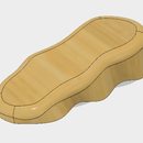
Create a new sketch on the back face and draw a rectangle with the top collinear to the top of the body that was just created. Stretch the rectangle downward so that it extends below the grip but the left and right sides are indented about 25 mm. Extrude it slightly less than the first extrusion.
Now add fillets/chamfers. Try to match the fillet/chamfers made to the main body grip as best as possible.
The last thing to be done to this piece is the cutout for the guide rail and main thread. The project command is the easiest way to recreate the exact shapes and locations of the cutouts. First activate the main overall design in the browser menu. Make sure both the main body and the sliding body are visible. In the "assemble" menu in the tool bar, click "joint" or press J. You'll have to set two points, one on each body, to tell Fusion where to line the parts up. Hover the curser around the middle of the Moving Body grip and select the circle that shows up in the middle. Next do the same thing on the main body side. Fusion will move the bodies so that they are lined up face to face.
Now reactivate the moving body and create a sketch on the back side. Hit P for project. Go to the browser and hide the sliding body(The main body should still be turn on as visible even thought it will show up faint). Click on the circle for the threaded hole and all of the lines that make up the guide shield hole. Turn the visibility for the Moving Body back on and the lines should show on your sketch. Cut these fully through the body and the component is complete.
Next we will tackle the main screw.
Step 6: Main Screw


Besides the main body and moving body, the main screw is perhaps the most important piece because without it, you don't have a vise.
Create a new component and draw a circle that matches the main screw hole on the main body. Extrude it approximately 90mm. You can come back and adjust this size if it is slightly off in the end.
Create another sketch on an end face and draw a center circle with a diameter about 5mm less than the previous circle. Extrude that out about 5mm. This section provides room for the lock that will hold the screw in place.
Create another sketch on the end face and draw a circle the same size as the very first one and extrude it out about 15mm. This piece will sit through the moving and the guide shield.
Note: This process can be done in just two steps but I prefer to see the sections build onto each other. You can also easily modify the length of each section individually this way.
Now add threading to this. Ill repeat again that I found the ISO Metric Trapezoidal threading works well with 3D printing. Offset this threading by about 5mm.
Again build another section on the end face but this time make the diameter of the circle a bit bigger than the rest. This section is to provide area on the guide shield/moving body to help push toward the main body as the threading is turned.
One last section needs to be added on the end to make space for the handle. I used the same dimension as the threaded part but it is flexible.
A hole is needed for the handle so start a sketch on the perpendicular plane and sketch a small circle in the middle of the body. Leave extra room on the end side of the rod for a fillet if you wish. Cut fully through the body.
Lastly create a fillet to round the end slightly.
Next up is the Main Screw Lock!
Step 7: Main Screw Lock


The main screw lock will hold the Moving Body to the screw when the vise is opening.
Begin by creating a new component as usual. This time, keep the Moving Body visible. Use the back face of the Moving Body as the sketch plane for the beginning sketch.
Use the project feature to one again pull the thread hole circle and guide plate lines into the current sketch.
From the center of the circle just pulled into this sketch, draw another circle with a diameter 5mm less. This will match the indentation on the Main screw so if you used a different dimeter there, use it here.
From the sides of this new inner circle, draw tangent lines downward.
Draw an overall rectangle encapsulating all of this to form a main body for this part. (Check the attached picture for reference)
When extruding, the parts around the circle area may be picky depending on how its drawn. The goal is to have the smaller circular cut out with straight tangent sides running downward. You may have to select multiple pieces in the sketch to achieve this. Again, reference the attached pictures to see how it should look.
Add chamfers or fillets if you wish to achieve the look you desire.
Next up, is the handle.
Step 8: Handle


The handle fits into the hole on the main thread to provide a means of torque to open and close the vise. It consist of two components: the main rod and an end piece that keeps the handle from falling off.
Start by creating a new component and sketch, drawing a center circle that matches the hole size in the main screw and extruding it out a reasonable length.
Knobs are needed to keep the handle contained in the hole. The knobs can be simple or complex so for the sake of this instructable, I went with simple. Create a sketch on one of the end faces and draw a circle with a larger diameter than the existing body. Extrude it a few millimeters and then add some chamfers or fillets to smooth it down a little bit.
On the opposite end face, cut a few millimeter deep hole to allow an end piece to be "plugged" into it.
Create a new component to act as the end knob. Extrude a cylinder that matches the one just created on the end of the handle and add the same fillets or chamfers that were used.
On one of the end faces draw a center circle matching the diameter of the cut in the main handle piece and extrude it to the same depth or slightly less.
Threads can be created for these pieces or glue can be used to bond them together.
The next and last piece is the guide shield.
Step 9: GuideShield


The last piece of the puzzle is the guide shield as I like to call it. It has several functions with the first being that it shields any object in the vise from messing with the threading. Secondly it acts as a guide for the moving body to follow instead of rotating when the vise is opening and closing. Finally it sits in a groove between the moving body and the main screw providing push when the vise closes.
To begin, create a new component and make sure the moving body is visible.
Create a new sketch on the back face of the moving body and project the guide shield hold into it. Extrude it about 100mm (I used 105). You can come back and adjust this later if need be.
Start another sketch on the end face of the extrusion you just created and project the thread hole up from the moving body.
Offset the guide shield lines outward a few millimeters and draw some sort of shape from the edges of it reaching down and around the entire thread hole. The idea is to create a surface that will sit in between the main thread body and the moving body. Extrude everything out about 4mm except for the thread hole.
That wraps up all of the pieces needed to build the vise.
Using the joint feature in Fusion, you can put together the completed model. Make sure to ground the base first and use sliders to get the correct axis of movement for the Moving Body! This isn't necessary to 3D print but it's fun to see the end result before you do!
Step 10: 3D Print


Fusion 360 makes printing designs incredibly easy.
Go to the toolbar and click on the "make" button, in the dropdown menu click on "3D print".
Click on the component that you'd like to print and then you have two options. If you check "Send to 3D Print Utility", it will allow you to directly send it to Cura (or whichever your favorite slicing software is). If you do not select this, it will allow you to save the object as an stl file to later import into a printing utility.
From my estimates, this print takes roughly 100 meters of filament so make sure that you have a solid kg roll before beginning!
And there you have it! Thanks for stopping by! Be sure to leave any suggestions or questions as tweaks will surely be made in the future!

Participated in the
Makerspace Contest 2017

Participated in the
First Time Author Contest


