

Introduction: Air Hockey Robot EVO


A challenging robot, perfect to have fun and learn robotics at the same time
It is fast, stable, easily modifiable and shares the electronics and ancillary elements with others jjRobots like the iBoardbot, B-robot EVO. Sphere-O-Bot (and more to come!)
With the idea of using standard 3D printer parts : NEMA17 stepper motors, stepper motor drivers, the jjRobots Brain Shield, belts , bearings, rods, 3D printed pieces … we started to develop the project. The main advantage of using these parts is that they are inexpensive and easily available. We have chosen a medium size Air Hockey table from a well known online seller to deploy the robot on: We wanted something easily transportable but comfortable to play with. The final dimensions of this Air Hockey table are 90x43cm.
Step 1: The Air Hockey Robot EVO Has Been Seen At...

Step 2:

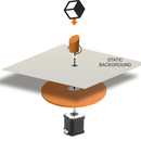
The Air Hockey Robot consist in three different parts: The Air hockey table, the Robot itself and your own smartphone.
Your smartphone, running the Air Hockey Robot APP (free APP), can detect features on the playing court and make decisions according to the detected objects location and theirs trajectories (and attack/defend in consequence).
Step 3: HOW DOES THIS ROBOT WORK?


The smartphone´s camera(2) is looking at the playing court . The camera´s captured data is processed in real time by the smartphone. Detecting the position of the puck and the “Pusher robot” (and according to the current location of all the elements on the court), your smartphone makes decisions and commands the Robot (3) via WIFI (1).
Your smartphone will become an augmented reality device, showing predicted trajectories and position of all the objects involved in this game. The Robot is locally controlled by the jjRobots Brain Shield (1) which dictates the speed and acceleration of the robot, sending the appropriate pulses to the stepper motors. Easy!
Step 4: CONTROLLING THE ROBOT


We have developed an APP to control the Air Hockey Robot. It is freely available on Google Play. The idea was to use the portable computer that you have "always" with you (we are talking about your smartphone :-D ) to control the Robot. As the smartphone already has a good camera and extremely powerful processor, why not making the most of it?
There are two options to control the Air Hockey Robot: Let your smartphone control it (AUTO) or the Manual control: take control of the robot using your finger (move the robot wherever you want). Feel free to download the APP and check both options (you do not need the hardware to play with the APP.)
If you download the APP keep this in mind: As the smartphone (in order to control the game) will look for two different things (the robot and the PUCK locations) two different small circles (green and blue foam circles) will tell where both elements are in the playing court. Take a look to the photos showing the foam circles. The APP can be set to detect any other colour instead the default ones (via the setting menu) but the diameters have to be: 2 cm for the robot, and 4 for the PUCK. If you print the 3D parts by yourself, do not use the same colours used for the foam circles or the robot will get confused!
NOTE: The APP will celebrate if you score and have funny sounds of the crowd cheering up when the puck speed up :-D
Step 5: How to Create One. STEP 1: What You Need. BOM


If you want to support jjRobots, you can get the OFFICIAL Air Hockey Robot EVO KIT from here. Optionally you can get everything by yourself and manufacture the jjRobots Brain Shield (info available here).
We have published an ASSEMBLY GUIDE here. The FORUM is always available too for everyone who wants to share ideas and ask for help.
A short FAQ about the robot here
BILL OF MATERIALS:
- 12x M3 bolt 6mm
- 4x M3 bolt 10mm
- 6x M3 bolt 15mm
- 7x M3 bolt 25 mm
- 20x M3 nuts
- 2x M3 self blocking nut
- 12x M2.5 Wood screw 20 mm
- EVA FOAM (two different colours)
- 4cm 12V FAN
- 2x Stepper motor NEMA17 + cables (70+70 cms)
- jjRobots Brain Shield
- Arduino Leonardo
- 2x Stepper motor drivers A4988 + heatsinks
- 12V 2A power supply 5.5mm 2.5mm jack
- 2x LM88UU linear ball bearing
- 12x 623 ball bearings
- 2x Stainless steel bar 8⌀ 455mm long
- 2x Anodised aluminium tube 8⌀ 43.5 mm long
- 1x Aluminium square pipe 12×12 mm 71cmGT2 timing belt (300 cm)
- 5x zip ties (150mm x 3 mm)
- double side sticky foam
- 3D printed parts (link to Thingiverse)
- Air hockey table
- Android Smartphone (Lollipop OS or higher)
- Smartphone holder
Step 6: Some Comments Before Proceeding


The key for assembling a flawless working robot is the H-bot system: this structure allows the robot to move itself to any location on its playing field only using two motors. Can be detached easily so you can use the Air Hockey robot as a Air hockey table whenever you want.
You need this H-bot to run smooth and be strong at the same time. The better you set it up, the higher the accelerations you can reach with your robot. Pay attention to the tips provided throughout this guide. The other thing to be aware of: vision system. The smartphone camera is capable of capturing up to 30 frames per second. Doing that, the robot can calculate precisely the position (and in consequence, its trajectory ) of both the robot and the puck.
VISION SYSTEM: The coordinates of the puck and its trajectory are calculated using the visual data coming from the smartphone´s camera . Two consecutive frames are required in order to calculate the trajectory of the puck. The Air hockey robot uses its current location, the puck position and the trajectory prediction to determine its strategy – either defence, defence and attack, or a new attack. An uniform illumination is extremely important for the vision system. Avoid shadows, reflections (and if you can, fluorescent lighting).
The Air Hockey robot uses two powerful stepper motors. Keep an eye on where you place your fingers!.
Sudden accelerations of the robot within its playing area could catch you unaware. Before adjusting anything remember to disconnect its power supply.
Remember to print the parts listed in the Thingiverse webpage (or get them from us) before the set-up process
Assembling the robot might take from 40 min to nearly 2 hours. The most important thing: the h-bot structure has to move smoothly. If you notice friction, use olive oil.
Step 7: Assembling the H-bot Structure


Assuming you have already printed all the parts and have all the hardware. Lets start with the H-bot structure.
Use 6x 6mm M3 bolts (3 per motor) to fix the motor to the motor supports
Place the 623 ball bearings (12 units, 2 per pulley) inside the plastic pulleys as indicated above.
Step 8: Fan: Cooling Down the Electronics

Use 4x 15mm M3 bolts and 4 M3 nuts to fix the FAN to its support
Step 9: Horizontal Axis


Take the 2 aluminium pipes and insert both in the LATERAL SLIDER piece. This is the most important part of this assembly guide. It could seem quite hard to insert the pipes into the 3D printed parts, but the sturdiness of the structure will depend on how tight everything is. Use a hammer (gently) if you want to push the aluminium pipes into the channel. Twist the pipes as you are pushing them could help during the insertion. Before placing the second LATERAL SLIDER cap, insert the bushings (red in the photo above)
Now it is time to screw the pulleys you have assembled before. There is no need to use a nut to fix the bolts. Just screw them. Use zip ties to hold the pusher in place (x4). Just hug the plastic bushings with the zip ties as you run them through the pusher piece (there are two channels for that)
Check there is not friction on this structure. Olive oil will greatly reduce the friction between the aluminium and PLA plastic: https://www.jjrobots.com/wp-content/uploads/2016/12/checking-movement.mp4
Step 10: Robot Pusher

Use 4x 15mm bolts to fix the base of the PUSHER. All the photos above show how it looks after placing it
Step 11:


Now, take 4x M3 10mm bolts + 4 nuts to fix the pulleys to the motors axis. They have to be tight. These pulleys will transmit all the movement to the robot. If they are loose, the robot will misbehave.
side supports. Use a pulley (the ones with the 2x 623 ball bearings inside) and fix it the both side supports using a self-locking nut. Once finished, insert the steel bar into the side support.
Step 12:

We are almost finished here. Insert the LM88UUs into the steel bars as indicated above. Do not forget this step! After placing the linear bearings (LM88UU), insert the steel bars into the motor´s support. Now you are ready to set everything on the Air hockey table.
NOTE: the "default" Air hockey table used for this robot is one worldwide available, distributed by Athleteshop. But you do not really have to get this one. The Robot can be adjusted to any others air hockey tables with similar dimension (90x40 cms) there is not limitation on the APP side. The limitation comes with the hardware: the motors and H-bot structure will not be able to handle a 2x1 meter air hockey table.
Step 13:


Screw off the top screw and place the motor support in place. There is video here: http://www.jjrobots.com/air-hockey-robot-evo-assem... showing up how to do this step (We can not upload it to the Instructables webpage)
Fix the side supports using two wood screws.
Step 14:

Push, gently, the X-axis robot structure into the LM8UU linear bearings. Check the video here
Step 15: HARDWARE/ ELECTRONICS

Electronics: Elements needed to control the Robot: jjRobots Brain Shield, Arduino Leonardo, 2x Stepper motor drivers (+heatsinks), FAN (12v) and 3D parts support + bolts/nuts
In the photo: All the electronics correctly set. Pay attention to the stepper motor drivers orientation.
Step 16:


Use 3 screws to fix the Arduino Leonardo to the Air hockey table (next to the motor). Then, connect the Brain Shield and finally, the stepper motor drivers.
Place the FAN on top of everything and connect it to the VIN output of the jjRobots BRAIN SHIELD. There is only one way to connect it, but just in case, take a look to the electrical diagram. Finally, connect the motor cables.
DOUBLE CHECK THE POLARITIES! The stepper motors can handle an inverted polarity but the FAN can not say the same.
NOTE:
Always, always keep the FAN blowing while the Air Hockey Robot is working. The stepper motor drivers might get damaged is there is not a constant air flow cooling them down
Step 17: AIR HOCKEY ROBOT VISION SYSTEM (A.K.A. Your Own Smartphone)


Use three screws (location indicated by the yellow arrow) to fix the POLE SUPPORT to the Air hockey table. Place it 2 cms away from the edge where the Air hockey table´s Goal will be placed.
if you set the GOAL in place, you should have something like the photo above (note: the motors are not connected in the photo)
Step 18: Placing the Smartphone As the Camera


Use a 25mm long bolt and a wingnut to hold the smartphone support to the pole. Fix the smartphone holder using the camera bolt too. The camera of the smartphone has to be on the left side (pointed by the red arrow on the photo above)
Install the control APP and start it up. Place the smartphone on the holder and point to the playing court. Take a look to the video in the assembly guide to know how to calibrate the point of view
NOTE:
In order to connect the APP to the Air Hockey Robot, you will need to connect your smartphone to the “JJROBOTS_XX” WIFI NETWORK using the password: 87654321
Step 19: Creating the Colour Features: Things to Be Detected by the Robot


Cut the GREEN EVA foam with the shape of the PUCK (use it to draw its shape on the foam and then cut it). Stick it to the PUCK using the double side tape (provided with the KIT)
Cut a 20mm diameter circle of BLUE FOAM and place it as above. Use the double side tape to stick it.
Why using FOAM and not a 3D printed feature or…a sticker?
Due to the FOAM anti-reflective capacity. Keep in mind that the ROBOT VISION SYSTEM can be tricked by FAKE reflections on a plastic surface. The ROBOT is not just detecting a colour but two features: SIZE AND COLOUR
NOTE:
An uniform illumination is extremely important for the vision system. Avoid shadows, reflections (and if you can, fluorescent lighting).
Step 20: PROGRAMMING THE ARDUINO LEONARDO

STEPS:
- Download the ARDUINO CODE from HERE (or go to jjRobots GITHUB REPOSITORY and download it from there)
- Connect the USB cable provided to the Arduino LEONARDO
- Compile the CODE using the ARDUINO IDE (The CODE is compiling and has been tested under ARDUINO IDE 1.6.12) and upload it
You have to select the ARDUINO LEONARDO as the default board and its PORT in the “TOOLS” MENU
Step 21: CHECKING THE ROBOT H-BOT AND MOTORS


Well, it is time to check the Robot movement skills. The jjRobots Brain Shield has a button placed between the motors connectors
Push it if you want the robot to make a MOVEMENT TEST PATTERN . This will let you know if everything is fine with the structure and motor control. This is the first time you will see how the robot moves by itself, so do not place anything on the air hockey table and be careful with your fingers!
BEFORE TURNING IT ON: PLACE THE TIMING BELT IN THE H-BOT STRUCTURE. IMPORTANT: DO NOT TIGHTEN THE BELT TOO MUCH, CONTRARY TO THE “LOGIC” A VERY STIFF BELT WILL NOT LET EVERYTHING TO MOVE SMOOTHLY
- If your robot is not making the TEST pattern, read below and find your problem:
- The robot is crashing against one side of the air hockey table: check the polarity of the motor cables.
I am hearing a cracking noise coming from the motor/s and the robot does not move at all or not enough to draw the pattern: the stepper motors can not move the robot due to lack of power. This can be caused by:There is too much friction in the H-bot structure: Check everything again. Is the timing belt too tight? Try to adjust the STEPPER MOTOR DRIVERS output current via its potentiometer
MUCH MORE INFO AND TROUBLESHOOTING (updated) HERE: http://www.jjrobots.com/air-hockey-robot-evo-assembly-guide-v-1-2/
QUESTIONS, COMMENTS, PROBLEMS?. GET TO THE AIR HOCKEY ROBOT FORUM HERE
Step 22: GET THE AIR HOCKEY ROBOT KIT

We really hope you liked this robot. We have been working hard to make it... perfect for a community like Instructables. The APP has been created keeping in mind that it had to be compatible with many air hockey tables and configurations. All the Arduino code and hardware is OPEN SOURCE. If you have any ideas or comments, please let us know!
If you want to get the Air hockey hardware +ancillary elements + electronics + even the 3D parts from us:
.
You can get your customised KIT from here (jjrobots shop)
..
Air hockey table (recommended but not the only you can use) here
Assembly guide + troubleshooting here
Community here
GITHUB repository here
3D parts models here
Follow us on twitter to know updates of this robot and new OPEN SOURCE robots releases!
Follow @jjrobots
Step 23: Other OPEN SOURCE Robots Created Using the Same Electronics + Ancillary Elements


iBoardbot:
The iBoardbot is a robot connected to the internet capable of writing texts and drawing with great precision. Also, it can erase in a quick and effective way. Send to your iBoardbot your information from any part of the world. As it has a multi-user interface you can also play and challenge your kids, use it as a collaborative notice board or as a twitter wall in your shop window.
The fastest self balancing robot (remotely controlled using your own smartphone). Take a look to its skills!
Looking for robotic challenges? Visit the B-robot EVO academy
Control APP freely available in Google Play
The Sphere-O-bot is a friendly art robot that can draw on spherical or egg-shaped objects from the size of a ping pong ball to a large duck egg (4-9 cm). KIT here


![Tim's Mechanical Spider Leg [LU9685-20CU]](https://content.instructables.com/FFB/5R4I/LVKZ6G6R/FFB5R4ILVKZ6G6R.png?auto=webp&crop=1.2%3A1&frame=1&width=306)


