

Introduction: Arduino Pragotron TFT Clock Controller


These large Eastern European railway/factory clocks with their retro/industrial look are now very popular and can be seen for sale in trendy antique shops or architectural salvage dealers in London.
Many clocks supplied from these shops have had their original one minute drive movements removed and replaced by quartz movements. This is because they were designed to be driven off a Master Clock from a 12v to 60v supply and pulsed once per minute.
Although they work perfectly well and keep reasonable time these quartz modified clocks lose their original look and feel as they now tick once a second and no longer have the animated step forward of the hands and soft "clunk sound" once every minute.
This master clock circuit enables the original 24 volt movement to be used, powered from an Arduino Microprocessor with time synchronised to the "atomic" time source in Germany. The Arduino 5 volts supply is used to drive the clock movement via a voltage step up module. The circuit has a modular design to keep the design simple and build time short.
The animation above shows how the clock is stepped once a minute by the clock controller. The clock controller is of course hidden away and can be completely remote from the clock connected only by a pair of wires.
Although designed to drive Pragotron clocks this circuit should be able to drive any other clock that uses a polarised pulse
Step 1: Features & Functions

Picture above shows my Pragotron clock on the wall of my 1960's house.
Circuit Features/Functions
"Atomic" DCF77 clock synchronization for perfect timekeeping
Optional DCF77 signal repeater/multiplier included
Automatic summer advance/winter retard
Battery backup
Full Westminster chime of hours and 4 quarters
Clock advanced only once per minute as original
Only 5 volt power supply required.
Modular design on vero board add/remove features as required
Includes various pulse outputs for driving/synchronising other clocks/circuit
Detail
This clock circuit uses an Atmega 328 microprocessor to drive Pragotron type clock movements from a 5 volt supply. The Arduino Code is based on my Master Clock code and has been completely re-written for Udo Klein's V3 library by Peter Hillyer. Peter has added code for a 2.2" TFT SPI display and sound via a JQ6500 sound module controlled over the serial port.
It should also be able to drive other clock movements that require a 1 minute alternating pulse to drive them. Pragotron movements have different drive voltages so a step up voltage module is used to set the correct voltage for the movement in use.
A DCF77 receiver module is used to synchronize time to the "Atomic" Clock in Germany and clock functions and controls are monitored on a 2.2" TFT display.
The circuit is built onto Vero Board and can be located remote from the clock movement that is being driven. An off the shelf Arduino Uno can be used but will required a 16MHz quartz crystal added in place of it's built in 16MHz resonator. Other Arduino boards can also be used but must use a quartz crystal for the microprocessor timings as this clock design uses Udo Klein's DCF77 library. See details here UNO Mod
Switches are mounted on the Vero Board to start Auto summer advance and also winter retard. Full Westminster Chimes including volume are controlled by the Arduino and played through a JQ6500 sound module and chimes can be set to On, Off and timed. Battery backup is provided by 3 x 1.5v Alkaline batteries and will keep the clock running without chimes during power cuts. This circuit also includes a DCF77 "repeater" and "multiplier" circuit and can provide DCF77 pulses at 5volts to other clocks. This and the Westminster chimes cam be omitted if not required. Full details can be found in the sections below.
Step 2: Re-fitting Original Pragotron Movement


Pragotron PS100 Movement Case Details
The PS100 movement case measures 60mm x 80mm x 20mm the terminals at the bottom of the movement are 10mm long and the minute shaft protrudes around 15mm from the face of the case. The hand adjuster a further 5mm from the back of the movement.
Removing the old quartz movement
To get to the old movement to remove it place the clock on it's face on a soft cloth to protect it from damage.
see picture 01
Remove four bolts highlighted by yellow arrows and take out the four L shaped brackets and single hanging bracket on the top.
Carefully remove the dial with the quartz movement attached from the clock case. The dial is very thin and is easily bent if handled incorrectly. First remove the minute hand by undoing the brass grub screw under the minute hand holding it to the minute shaft. See red arrow.
The hour hand should be a friction fit and can be gently pulled off. Now unscrew the collar holding the quartz movement to the dial and remove the movement. On my clock the old Pragotron fixing bolts were filled down and glued over the fixing holes on the dial. Remove these bolts and discard.
Pragotron PS100 Movement Modification - adding a thermal fuse
I use a common power supply to drive my many clocks and these can deliver 8 amps of current. Each clock has it's own fuse but as a failsafe I have fitted a thermal fuse inside the PS100 movement in case the coil overheats. To fit the fuse the case will need to be taken apart and this means drilling out the welded studs in the case with the possibility of destroying your movement. If you don't want/need to fit the thermal fuse then just ignore the following.
The case is not designed to be opened and is secured with welded plastic studs in the four corner holes
seen from the the front of the case. To take the movement apart the plastic welds are drilled out using a 4mm drill. The top and bottom of the case can then be carefully prised apart.
Once the case is apart you find the movement is split in two.
Picture 3 shows the hour drive cog and shaft with adjustment cog along with the drive coil, rotor, stator and connector terminals.
Picture 4 shows the top half of the movement containing the minute shaft drive and rotor/adjustment cog.
Behind the minute shaft cog is a sprung metal plate that pushes the minute cog away from the plate ensuring engagement with the plastic hour drive cog.
Picture 5 shows the thermal fuse fixed to the drive coil with a twisted length of wire. In the event of the drive coil overheating the fuse will trip disconnecting the coil.
The fuse wire (slate white) is connected in series to one of the brown coil wires near the terminal block.
Re-fitting the case is a bit tricky.
Put the spring plate under minute shaft cog and press in under the rotor cog and it should hold in place. With a finger holding the hour shaft in place from the outside gently press the two parts together and with a bit of wiggling they should click into place. Turn the hand adjuster to ensure the movement is free. The two case parts can then be secured with plastic tape or some hot melt glue.
Fitting Pragotron movement
Pragotron movements are fixed to the dial by 3 bolts in a downward pointing triangle like the Pragotron logo around the minute/hour shaft (picture 3). My original bolts had been destroyed by the shop when converting it to quartz drive.
I found that M3 bolts fitted the tapped plastic case threads. I cut them to size just enough to go through the dial and movement case without interfering with the movement inside.
Re-fitting Movement & Dial
The dial with PS100 movement attached can now be refitted in the case.
With the clock case face down on a soft cloth lower the dial into the case and centralise it.
Put the left, right and bottom L shaped brackets back in the clock and re-fit the bolts removed earlier.
The top L shaped bracket has the hanging bracket slid down next to it before the fixing bolt is tightened up.
Step 3: Pragotron Movement Operation

Pragotron PS100 Lavet Type Stepper Motor Movement Operation
Specs
Coil Voltage 24volts
Coil Resistance 4000Ω
Coil Drive Current 8mA
Drive Type 1 minute pulse reversing polarity
The movement uses the Lavet type stepping motor action.
In the animation above the Minute hand shaft, attached cog and rotor drive cog have been removed for clarity.
The rotor is a permanent magnet with it's opposing poles are shown by the red and green dots.
Start:
With the stator coil non energised the stators have no magnetic field and the rotor will be stationary in it's last energised position.
When the 1 minute pulse of 24volts is applied with an opposite polarity to the previous pulse the stators become magnetised with their North and South matching the rotor poles. The rotor is then forced around clockwise and stops with it's North and South poles opposite the North and South poles of the stator.
The rotation of the rotor drives the movement forward 1 minute. The 24 volt 1 minute pulse is then removed also removing the stator magnetic field. The rotor stays where is was.
The next minute the another 1 minute pulse is received with the opposite polarity to the previous pulse. The stator is then energised with it's poles reversed matching the polarity of the stationary rotor.
The rotor is again forced around clockwise and stops with it's North and South poles opposite the North and South poles of the stator. The rotation of the rotor drives the movement forward 1 minute.
The 24 volt 1 minute pulse is then removed also removing the stator magnetic field. The rotor stays where is was and it has now turned 1 full revolution ready for the whole process to repeat from the start: above.
Step 4: UNO Quartz Crystal Mod


Time keeping
I have decided to use the DCF77 signal from the Atomic Clock in Germany. I could have used the MSF signal from the UK but reception is not good where I live in Surrey as the transmitter has now been moved further North. The DCF77 signal is also better supported as it is used across Europe not just the UK. I will be using the Arduino DCF77 decoder library written by Udo Klein . Udo has been developing this code over the last few years to make it synchronize and lock onto a signal even when there is a massive amount of noise and interference on the signal. While prototyping my new clock I consistently manage to synchronize and maintain a lock even though the DCF77 signal receiver LED that should show a steady 1 second pulse from Germany is flashing multiple times a second.
Udo's DCF77 library code is very very complex but in very basic terms it locks onto the DCF77 frequency using a phased-locked loop and once locked it will actually predict what the DCF77 code should contain and then look for snippets of this code in a very noisy signal. As things like the date do not change that often his code can look for this data in the signal to help it stay locked on!
Once in sync with the DCF77 signal it uses it to "auto tune" the backup quartz crystal ensuring if the DCF77 signal is lost the clock still stays in sync. You can read full details of the development of this library and much more on Udo's site/blog here Blinkenlight. The only small down side to this library is that it needs an accurate time base on the Arduino to lock into the DCF77 frequency.
My DIY Arduino built on Vero board uses a quartz crystal work fine however, modern Arduino boards don't use a quartz crystal ( the one you see on the board is for the serial port) but an inferior 16MHz ceramic resonator.
If you want to use a prebuilt Arduino you will probably have to do a small modification to the board.
Udo has written a test program to check if your Arduino boards resonator/crystal are up to the job of running his library and can be found here DCF77 Scope . If your board is not up to the job it is very easy to remove the resonator and replace it with a quartz crystal and a couple of capacitors. I have modified my Arduino UNO I used to prototype this circuit and it works perfectly with the library.
The Mod
Picture 1 shows the old resonator and resistor position and then the connections of the new capacitors and quartz crystal on the Arduino UNO board.
Picture 2 shows the completed mod on an Arduino UNO.
Picture 3 shows the original schematic of the resonator and resistor
Picture 4 shows the modified board with the quartz crystal and capacitors.
The quartz crystal and capacitors can be purchased as a kit from many online electrical stores/Ebay.
Step 5: Full Westminster Chime


Sound is via a JQ6500 Sound Module.
TheJQ6500 MP3 is a hardware decoder and can use MP3 and WMV files. The software supports TF card driver, spi flash update on the computer, and FAT16, FAT32 file system. Through simple serial commands, it can execute sound files. Sound files and volume can also be played using hardware switches.
The Arduino directly communicates with the sound module over the serial port. Some of the JQ6500 pins require 3.3volts so a level converter is used to convert the 5v Arduino output to 3.3volts.
Sound files
Sound files are loaded to the module via a USB lead from a windows PC.
The full Westminster type chime used in this clock requires 15 files all sampled @ 48kbps.
The files are named 001 to 015.
001 to 012 are the full quarter Westminster Chime followed by the number of chimes for the hour.
For example
001.mp3 contains the full Westminster chime followed by 1 hour chime.
002.mp3 contains the full Westminster chime followed by 2 hour chimes.
003.mp3 contains the full Westminster chime followed by 3 hour chimes.
etc, etc until
012.mp3 contains the full Westminster chime followed by 12 hour chimes.
013.mp3 contains the quarter hour Westminster chime.
014.mp3 contains the half hour Westminster chime.
015.mp3 contains the three quarter Westminster chime.
Loading sound files
Adding Sound to the Module
Plug the module into your Windows PC and run the file MusicDownloader.exe on the module.
A new window will pop up see picture 3.
Click on the 2nd tab then click on the button to the right of the blank box picture 4.
A file requester will open. Select your sound files and click on Open picture 5.
Go back to the first tab and click the button after a short delay the files will start to be copied picture 6.
When complete you will get this message picture 7.
Further info on this module can be found here JQ9500 info
UHD Video showing clock chiming
Details of the clock chiming the quarters and hour can be seen by viewing the enclosed video (picture 8).
I have used hand bells and a long case clock bell samples as the bases for my chimes but any sound can be used.
My Sound Files
You can download my sound files by downloaded the sound.zip file above.
Quarter Chimes
Sounds are sampled from handbells. Each individual note for each quarter is mixed on Audacity on seperate tracks and saved as a sound file for loading into the sound board.
There are four Quarter sounds played in this order.
First Quarter Notes: fagc
Half Hour Notes: fagc cgaf
Third Quarter Notes: fagc cgaf agfc
Full Hour: fagc cgaf agfc cgaf
These are not exact musical compositions and I just mixed them by ear so they sounded right to me!
Hour Chime
The hour chime is a sampled 4” longcase clock bell and a mix of handbells some slightly out of phase to simulate clock chime hammers striking bells a fraction out of time.
There are two hour chime samples a short and a long sample. The short sample last 2 seconds and replecates a hammer hitting a bell then stopping suddenly as the hammer strikes the same bell again.
This is used for all hour chimming except for the last chime where the long sample lasting 9 seconds is played. The long sample plays the full chime ringing out and fading away to nothing as a real clock would.
Speaker
I have added a small speaker to sound the chimes and it is mounted in a small plywood enclosure see picture 2.
It is small enough to mount behind the dial if required or can be mounted remote from the clock.
Attachments

Step 6: TFT Display


TFT Module
Picture 1 shows the full range of information on the display over a minute.
Picture 2 shows the front of the display module
Picture 3 shows the rear of the module.
The 2.2" LCD in the TFT01 is a IL19341 and has a 240 * 320 resolution.
Pins
SDO: Serial clock output
LED: 3.4V Power Supply pin
SCL: Serial clock input
SDA / SDI: Serial data input
DC: Data / Command selection
RST: Reset, Low level active
CS: Chip Selection, Low level active
GND: Ground
VDD33: 3.3V Power Supply pin
A level converter is used between the Arduino and some of the TFT display pins as they require 3.3v. See schematic for details.
The display is split into 5 sections.
The first shows the current decoded time and date from the DCF77 transmitter
The 2nd row shows the following information: Makers name and S/W version Time first synchronised. This will show you the length of time the clock has been running.
Quartz accuracy and Quartz frequency. The quartz crystal is only used when the DCF77 signal is lost and while the clock is in sync the quartz crystal in continuously "tuned" to the highly accurate DF77 signal. This row will show the actual "tuned" frequency of the quartz crystal along with the accuracy in Htz with 1Htz being the best.
Seconds lost or gained. This will show the number of times the clock has been out of sync with the DCF77 clock and auto corrected for more and less than 1 second. This is useful if the clock is driving 1 second slave clocks as they could be out of sync if the auto correction fails. The auto correction adds or removes a 1 second pulse to maintain sync of the 1 second slaves. You would expect a 1 second loss to be registered for example when a leap second is injected.
The 3rd row shows the DCF77 signal status and quality
The 4th row has the BST (british summer time) indicator and slave pulse output monitor The 5th row is the chime status monitor. Chime is green when chimes are always on, yellow when on timer and off when chimes are off.
Step 7: H Bridge Module

Dual H Bridge Module
I have connected my clock movement to connection 02.
Important remove link from the onboard regulator as shown as this is not used.
5v is derived from the Arduino power supply to the screw terminal marked "5v Arduino"
Ground is common ground and 24v is the stepped up supply from the step up module
Remove the link from ENA and ENB as the H bridge is enabled from the Arduino.
I have connected ENB to my Arduino as I am using output 2.
Whenever ENB is set to 5v from the Arduino whatever 5v voltage polarity set on IN3 & IN4 pins from the Arduino is sent out at 24v from the H bridge module to step the clock on 1 minute.
H bridge Module specifications from manufaturer
L298N as main chip Low heat,outstanding anti-interference performance.
High working voltage up to 46v
large current can reach 3A MAX and continuous current is 2A
power up to 25w.
Can drive one 2-phase stepper motor, one 4-phase stepper motor or two DC motors.
Built-in 78M05, get power from drive power, however, when drive power over 12V, please use the external 5v power as power supply.
Large capacity filter capacitance, afterflow protection diode, more stable and reliable.
Specification:
Double H bridge drive Chip: L298N (ST NEW)
Logical voltage: 5V
Drive voltage: 5V-35V
Logical current: 0mA-36mA
Drive current: 2A(MAX single bridge)
Max power: 25W
Size:43 x 43 x 26mm(LxWxH)
Note:
This module has a built-in 5v power supply, when the driving voltage is 7v-35v, this supply is suitable for power supply DO NOT input voltage to +5v supply interface, however leading out 5v for external use is available. When ENA enable IN1 IN2 control OUT1 OUT2 When ENB enable IN3 IN4 control OUT3 OUT4
Step 8: Level Converter & Step Up Module


Logic Level Converter Module
This module takes the 5v output from the Arduino and converts it to the 3.3v required by the TFT monitor inputs.
There are four inputs and four outputs on the module. The input voltage of 5v is set by the voltage on HV connector and the output voltage of 3.3v is set by the voltage on the LV connector. Both Gnd connectors are connected to Gnd.
The Arduino pins SCK, MOSI,TFT_CS & TFT_DC are connected to HV1 to HV4 and the TFT pins SCK, MOSI,TFT_CS & TFT_DC are connected to the associated LV pins LV1 to LV4.
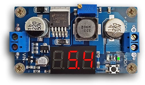
Voltage Step Up Module
The Pragotron LS100 movement requires 24v to operate so this module steps the 5v from the power supply up to 24v.
To set connect 5v and Gnd to the IN connector and with a voltmeter on OUT + &- adjust the variable resistor on the board until it reads 24v.
The module has four connections -&+ IN and -&+ OUT.
5v & 0v from the Arduino power goes to IN + /IN- and OUT + /OUT - goes to the H Bridge module 24v pin.
Step 9: Switches


There are nine switches all mounted on the main board for easy wiring.
Picture 1 shows switch location on main Vero board
Picture 2 shows switch labels
Switch Function Table
Switch Type Function
Reset 1 way non locking press On Reset Atemega 328 & TFT display
Chime Mode 1 way non locking press On Selects Chime mode between On Green, On preset times only Yel and Off
Advance 1 way non locking press On Advances the clock by 1 hour
Retard 1 way non locking press On Retards the clock by 1 hour
Cancel Adv/Rtd 1 way non locking press On Cancels advance or retard
Motor Sync 1 way non locking press On When first powered up or if the clock hands have been manually adjusted synchronises the motor with the H Bridge output
Volume- / Prev 1 way non locking press On Press to play previous sample on sound module Press and hold while playing to lower volume
Play/Stop 1 way non locking press On Press to play current sample on sound module Press again to stop playing
Volume+ / Next 1 way non locking press On Press to play next sample on sound module Press and hold while playing to increase volume
Step 10: Arduino Pin Connections

| IC Pin | IDE Pin | Function |
| 1 | Reset | Reset DCF77 Analyzer & TFT Display |
| 2 | 0 | Rx |
| 3 | 1 | Tx & Tx for sound module |
| 4 | 2 | Retard |
| 5 | 3 | Reset Advance/Retard |
| 6 | 4 | Chime Mode |
| 7 | NA | 4.4v |
| 8 | NA | Gnd |
| 9 | NA | Xtal1 |
| 10 | NA | Xtal2 |
| 11 | 5 | Advance |
| 12 | 6 | 30 second pulse |
| 13 | 7 | Clock 01 |
| 14 | 8 | Clock 02 |
| 15 | 9 | TFT DC |
| 16 | 10 | TFT CS |
| 17 | 11 | MOSI |
| 18 | 12 | MISO |
| 19 | 13 | SCK |
| 20 | NA | 4.4v |
| 21 | NA | AREF |
| 22 | NA | Gnd |
| 23 | A0 | enable01 |
| 24 | A1 | DCF LED |
| 25 | A2 | Motor Sync |
| 26 | A3 | Spare |
| 27 | A4 | DCF77 I/P |
| 28 | A5 | Chime Busy |
Step 11: Power & Battery Backup

Power Requirements
I use a common 12 volt power supply unit (picture 1) to drive many different types of clocks. This 12 volt supply is then stepped down locally at each clock with a step down module (picture 2) to supply power for the control board and various modules. Note I adjust the PSU to read 5 volts after the reverse protection diode D4 this makes sure the voltage is above the battery backup circuit.
If you are running just this one clock then any regulated 5 volt supply will do as long as it can supply the current for your circuit use. The configuration of modules in my particular circuit requires approximately 300mA to run at max power. This is with a 24v movement connected and chimes at a volume loud enough for a single room without disturbing other rooms in the house.
If you are driving higher voltage movements and or sounding chimes at very high volumes then current draw will go up.
Normally with the display off, the clock not stepping and not chiming the clock will draw 59mA.
Once per minute for around 0.5sec while the clock advances 1 minute the current will rise to 174mA.
If the chime is set then every 15 minutes for a few seconds as the Westminster Chime quarters are sounded the current will rise to 64mA to 174mA (depending on set volume).
Max current of upto 300mA is drawn on the hour for 0.5 seconds as the clock advances 1 minute and chimes out the hours.
I have fitted a 650mA fuse on the main board and also a thermal fuse in the clock movement as my common power supply can output many amps.
Battery backup
Battery backup is very simple and just uses 3 1.5v alkaline batteries and a diode D1. When power is supplied by the power supply unit no current flows from the batteries as the diode blocks it. If the power fails and the voltage drops below the battery voltage ( and the voltage drop of the diode) the batteries start to supply current through the diode keeping the clock running.
Step 12: Summer Advance


Summer Advance
To correct the clock for summer time (advance by 1 hour) just press the advance button on the main control panel. The Pragotron clock will start to advance and the display will show "BST advance count" and will count down as the clock advances an hour.
During summer advance if the current seconds get to 0 the advance count will stop for 1 count to ensure the clock advances exactly 1 hour. Once the advance count reaches 0 the clock stops advancing and the TFT display reverts to normal.
Picture 1 shows the TFT display counting the advance pulses when the advance button is pressed @ 10:09:23
Note the @ 10:10:00 the advance count stays at 23 and does not count down to 22 as expected. The is because there is a normal minute pulse expected at this time so this pulse is ignored. If this did not happen the clock would be 1 minute slow when the advance completes.
Picture 1 is a video showing the advance in operation on my clock
Step 13: Winter Retard

Winter Retard
These clock movements can not be stepped backwards so they are retarded by stopping the drive pulses for 1 hour.
To correct for winter time (retard by 1 hour) press the retard button on the main control panel. The TFT display will show "BST Retard count:60" and the Pragotron clock will stop. As each minute passes the Retard count will decrease by 1 until it reaches 0 when the Pragotron Clock will restart and the TFT display reverts to normal . The clock will be exactly 1 hour retarded.
Picture 1 is filmed in timelapse over 1 hour and shows the TFT counting down the missed pulses as the time on the top row moves forward.
Step 14: DCF77 Repeater/Multiplier


I have many clocks synchronised to the DCF77 "atomic" clock in Germany. via a DCF77 aerial and receiver circuit. Each clock requires it's own DCF77 signal so rather than having a separate DCF77 aerial and receiver circuit for each clock I have just one and feed the 3.3v output into my DCF77 Repeater/Multiplier circuit.
If you have only 1 clock that needs the DCF77 signal then this part of the circuit can be omitted.
Picture 1 shows the circuit on the main board with picture 2 the schematic.
The circuit uses a 6 way inverter. The 3.3v DCF77 signal from the receiver comes into the 1st inverter
and is inverted and changed to 5v. This is then fed to the remaining 5 inverter inputs. The output from each of these 5 inverters is then exactly the same as the incoming 3.3v DCF77 signal but is at 5v. Each output can be then sent to different DCF77 clocks.
Step 15: Vero Board Layout


The circuit is designed around prebuilt modules and is very easy to build onto Vero Board.
Board Layouts
Picture 1 shows the main board with working TFT display.
Picture 2 shows the actual layout of the board with all modules connected.
Picture 3 shows the board layout without the modules so component location,links and track cuts can be seen.
Picture 4 shows the rear of the board in picture 3 hinged at the bottom and flipped down so the track cuts are more visible.
Construction
Picture 5 shows all components mounted ready for final wiring.
The white temporary labelling strips helps position wires and components and is removed once they are all in place. The modules plug into the installed headers on the board once wiring is complete.
I start by placing the larger components like IC sockets and header strips on the board first. I tack these in place with a bit of solder on the top and bottom connectors. Once I am happy these are correct I cut any tracks between IC sockets then solder them in place along with the headers.
I then work my way around he board adding components and cutting tracks as I go. When soldering a component to the board I hold it in place with plastic tape flip the board over and solder it. This stage is shown in picture 5.
Once all the components have been connected I do the 5v, 3.3v and 0v runs with straps/insulated wires. These should be shown on the board layouts pictures 3 & 4.
To complete the board the wires interconnecting all the modules/components are added using the schematic diagram. I print out the schematic and as each wire is connected I tick it off the schematic to ensure no wires are missed out.
Once the wiring is completed I then "tap" the board out track by track with a multimeter on continuaty setting to check for any short circuits.
Finally the modules can be added to the completed board picture 6.
Picture 7 shows the module names. On my board the 3.3v module is omitted as it gets it's 3.3 volts from another clock in the same housing.
Step 16: Schematic

Picture 1 shows the full schematic.
Leave out modules and associated wiring as required.
The DCF77 receiver module is located remote from the clock and connected to the DCF77 repeater/multiplier or if this is not required direct to the Arduino DCF77 sample pin.
Step 17: Arduino Code
Arduino Code
Download Code V2.4 check for latest version on my web site here Check/download latest code
A standard Arduino Uno can be used but must have a Quartz Crystal added instead of a resonator to work with Udo Klein's DCF77 Library. See details here UNO Mod
DCF77 Library
Requires Udo Klein's V3 library https://blog.blinkenlight.net/2015/08/01/dcf77-library-release-3-0-0/


![Tim's Mechanical Spider Leg [LU9685-20CU]](https://content.instructables.com/FFB/5R4I/LVKZ6G6R/FFB5R4ILVKZ6G6R.png?auto=webp&crop=1.2%3A1&frame=1&width=306)


