

Introduction: Arduino Word Clock


Further details on this build on my site here Word Clock
Arduino Word Clock with minute resolution of time in words and linear display of seconds.
NEW 19/08/2022 Jason Groves has designd his own version of this clock on PCB. Full file download on my website.
NEW v4.6 onward a hidden switch enables/disables the touch sensors to prevent unauthorized clock setting.
NEW added Doppler Radar option. V4.5 the clock now checks for movement on the quarter hour and will turn off the display if no movement detected. Code v4.5 works for both PIR and Doppler Radar modules.
There are also modes for digital clock, analogue clock, temperature & humidity, & also three games, Game of Life, Simon & Tetris.
The clock can be stand alone or run as a slave off a Master Clock if required.
Without a Master clock time is controlled by the Word Clock's built in temperature compensated real time clock.
There is an option for PIR or Doppler Radar control so the clock automatically turns off when no one is in the room.
The Clock measures 500mm x 500mm (19.68" x19.68") weighs 12lb (5.5Kg) and is designed to be wall mounted. There are touch pads in each corner to setup and control the clock.
Edit 02/12/2018 Do not use automatic summer winter correction as there is a bug that causes the RTC to loose the time on power loss. Leave R5 connected to PIN D7 via 0v.
Edit 13/12/17 Corrected fault on touch sensors on Tetris game now v3.8
Credits
This clock is based on the original Word Clock by Wouter Devinck full details on his Instructable & GitHub and the "Catalan" Pijuana Word Clock software based on Wouter Devinck's clock (this is a fork off the original Wouter Devinck design) here GitHub.
Step 1: About Word Clocks


About Word Clocks
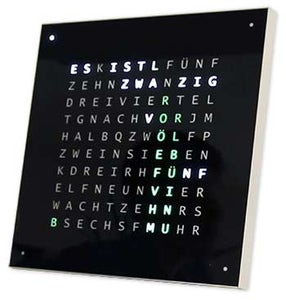
Word Clocks tell the time using a matrix of words or numbers and letters and have been around for many years. There are a few different design types around that affect the complexity of the clock build.
Photo 1
The simplest use blocks of words to tell the time in five minute resolution eg O'CLOCK, 5 PAST, 10 PAST etc. These clocks only use 20 or so individual LED blocks and therefore are the simplest to construct. The main disadvantage of these clocks is they can only show the time in this set format.
Photo 2
The medium level clock has a 11x10 matrix of LEDs plus four addition LEDs around the outside of the clock.
The Raspberry Pi controlled clock Photo 2 even has multicolour LEDs and as it has 110 individual LEDs it can display digits and basic images. These clock still use a 5 min resolution in words but often add "just gone 5 past" or almost 10 to" to increase the resolution slightly. Often the four LEDs around the corners of the frame indicate the passing four minutes to fill the gap between the 5 minute worded resolution. These clocks are reasonable complex to build and often use strips of LEDs to make the build easier.
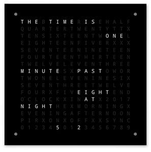
Photo 3
There are commercial versions of this type of clock available.
The 450mm wall hanging version cost around £1000 and features interchangeable front panels in many colours and materials as well as smaller desktop and watches are available.
Photo 4
256 matrix Word Clock by Wouter Devinck
The Word Clocks with the highest level of complexity use a 16x16 LED matrix giving a full 256 LEDs to control.
These clocks have a one minute worded resolution of time as well as morning, evening, night etc. They often tell the rough temperature in words like warm, very warm, cold very cold etc.
With the 256 LEDs to play with there are huge amounts of different display modes available. These clocks are quite complex to build due to the number of connections in the matrix display. Building the LED matrix on PCBs with surface mount components allows for very slim clock bodies and makes the display construction simpler but above 500mm x 500mm the PCBs start to get expensive.
Hand building the LED matrix as in my clock needs space and 500mm x 500mm is a good starting point as this can just about accommodate the large wiring looms needed to interconnect the LEDs and display modules. Very large wall filling clocks can be built using hand built LED matrixes.
Step 2: Changes


Changes
This clock is a mixture of the Wouter Devinck Clock hardware & the "Catalan" Pijuana clock software. I have not used any PCBs just ready made modules and three small Vero board circuits for the power.
The main changes are detailed below.
No custom PCBs are used in this version of the clock just cheap easy to come by prebuilt modules.
The main clock body is built from 2 x sheets of 14 mm MDF rather than a single 18mm sheet.
Photo 1
The rear sheet is 10mm smaller than the front sheet on all sides except the top so the clock appears to be only 14mm thick.
Photo 2
The Wouter Devinck clock is just 20mm deep including the 2mm glass whereas my clock is actually 34mm deep including the 4mm glass and 2mm dust seal on the rear. Due to the setback of the rear 14mm panel and the 1.5mm setback of the glass panel from most angles the clock only looks 14mm deep. This extra depth has allowed me to use a hand built LED matrix and wiring looms rather than 4 large PCBs. It also means I can use prebuilt maintenance friendly modules without surface mount ICs on the MAX7219 boards.
The main display is built direct to the display LEDs with no PCB so any size display is possible.
TTP223 Touch Sensor Modules are used instead of Azoteq IQS127D mounted on the main boards.
The display driver boards for the MAX7219 I/C use modified LED matrix boards. These boards come complete with all components.
An Arduino Nano is used to drive the clock due to it's small size.
A PIR sensor module is used to shutdown the display when no one is in the room (this can be disabled to keep the display always on).
A trimmer resistor is added to the circuit, accessible from the bottom of the clock with a small flat bladed screwdriver to calibrate the automatic display brightness.
Synchronisation to my master clock system every minute on 30 seconds. If no synchronisation pulse is available the clock will free run using the RTC. Synchronisation pulses are displayed on the main display.
The software is mainly based on the "Catalan" Pijuana version of the word clock so this has been translated into English for the display. Credits display modified from the "Catalan" Pijuana" version to show the current software version number, my name and also the year of build.
The worded temperature has been removed from the clock display and a linear seconds display added to the bottom row of the Word, Digital & Analogue clocks.
When the PIR is turned On or Off "PIR ON" or "PIR OFF" is displayed for a few seconds on the word clock display.
This clock uses a DS3231 AT24C32 I2C Precision Real Time Clock Module as per the Wouter Devinck Clock & the "Catalan" Pijuana clock. I am not keen on using the Lithium-Ion rechargeable battery that is supplied with the module. I use a non rechargeable battery and have modified the module to suit.
4mm float glass with polished edges replaces the 2mm glass. The glass is fixed to the main MDF board using Chicago Fasteners rather than glue. These also act as touch pads to control the clock and allows the glass can be removed if required.
Two dust seals are built into the clock, one on the rear panel and one behind the removable glass display panel. In clock setting Mode pressing the BOT Right button now resets seconds to 0.
The following changes to the English wording have been made to make the wording as I would say it. The way individuals say the time will vary from region to region depending on where you live/went to school etc etc. There is no correct way just the way that sound best to you.
Removed the words indicating the temperature on the word clock. These have been replaced with Sync status, PIR ON/OFF and Linear display of seconds.
Changed "MINUTES" to "MINUTE" at 1 minute past and 1 minute to the hour.
Added an "A" before the "QUARTER" past and "QUARTER" to the hour.
Added the missing "ELEVEN" from Wouter Devinck clock as per his notes.
At Midday changed the time to read TWELVE OCLOCK IN THE AFTERNOON.
At Midnight changed the time to read TWELVE OCLOCK AT NIGHT. After Midnight the clock will always say IN THE MORNING.
The "O'CLOCK" is now unpunctuated and just shows OCLOCK.
Step 3: Case Design


As my clock does not use custom Display Matrix PCBs with surface mount components my clock case has to be somewhat deeper than Wouter's design.
My case is 34mm deep and includes the rear dust seal 2mm, rear MDF board 14mm, front display board 14mm and 4mm float glass.
Wouter's case is just 21mm deep, 18mm single MDF panel and 2mm float glass.
Pic 1 shows the make up of the clock case layers.
In order to make my clock appear less bulky to the eye when mounted on the wall I have incorporated a few simple design features.
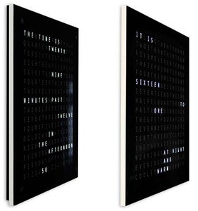
Pic 2 shows my clock on the left and Wouter's clock on the right. From an extreme side angle view you can clearly see my case looks bulkier.
This is offset somewhat by the rear board being black rather than white making your eye concentrate on the slim white 14mm edge. The rear board being 10mm shorter on the bottom and both sides enforces this illusion.
Pic 3 again my clock on the left and Wouter's clock on the right. The further towards the front of the clocks you go the shorter rear board on my clock disappears from view until only the slim 14mm front board is visible.
The 4mm glass is also cut 1-2mm shorter than the front board helping to hide it from view. My bulky 34mm clock case now appears to be as slim as Wouter's case.
Step 4: Controls

Controls
Photo 1 There are TTP223 touch control modules on the clock, top left, top right, bottom left and bottom right corners of the display.
The buttons have different functions depending on what mode the clock is in, see table Photo 2.
Step 5: Automatic Summer Winter Setting

Note there seems to be a problem with this in Summer Mode as it makes the RTC fail on loss of power.
Until I find a fix leave the BST pin connected to R5 and change summer and winter via the time setting menu.
~~~~~~~~~~~~~~~~~~~~~~~~~~~~~~~~~~~~~~~~~~~~~~~~~~~~~~~~~~~~~~~~~~~~~~~~~
Automatic Summer to Winter Change
Normally summer and winter time changes are made by manually changing the hour through the clock setting function.
The clock can be automatically set to summer or winter time by using the "BST" input on Digital pin 7.
5volts on this pin will add an hour and 0volts will take an hour off.
I have programmed one of my Pragotron Master Clocks to output 0v in wintertime and 5volts in summertime.
If you do not have a Master Clock and don't want to set the clock through the clock setting function you can just connect digital pin D7 on the NANO to 5volts via a switch as per the diagram below. When the switch is ON the clock shows summer time and when the switch is OFF winter time is displayed.
Step 6: Display Modes Clocks & Enviroment


Animation 1 shows the 4 clock and environment modes.
The modes are in order Word Clock, Digital Clock, Temperature & Humidity and Analogue Clock.
Animation 2 There is also a startup mode that scrolls through the software version number, makers name and name of the clock.
Step 7: Display Modes Games


Three classic games are coded into the clock. I have left the code as is from the Catalan Clock.
Animation 1 Conway's Game of Life
The universe of the Game of Life is an infinite two-dimensional orthogonal grid of square cells, each of which is in one of two possible states, alive or dead, or "populated" or "unpopulated".
Every cell interacts with its eight neighbours, which are the cells that are horizontally, vertically, or diagonally adjacent. At each step in time, the following transitions occur: Any live cell with fewer than two live neighbours dies, as if caused by underpopulation. Any live cell with two or three live neighbours lives on to the next generation. Any live cell with more than three live neighbours dies, as if by overpopulation. Any dead cell with exactly three live neighbours becomes a live cell, as if by reproduction.
The initial pattern constitutes the seed of the system. The first generation is created by applying the above rules simultaneously to every cell in the seed births and deaths occur simultaneously, and the discrete moment at which this happens is sometimes called a tick (in other words, each generation is a pure function of the preceding one). The rules continue to be applied repeatedly to create further generations.
Animation 2 Simon
Simon memory game- try and copy the computer generated sequence.
When entering your sequence double tap the last entry to end your turn.
When you fail your score is displayed on the screen.
Animation 3 Tetris
Tetris is the Soviet tile-matching puzzle video game released in June 1984.
This game still needs some work on the buttons to control the tiles correctly.
Step 8: Prototyping


Note correction to photo 1. I had drawn the pins 9 to 16 reversed. Thanks to member CFB70 for pointing this out.
The Clock can be prototyped and tested using the original DOT Matrix LEDs on the MAX7219 display boards.
Note this temporary modification is only required if you want to test your code on the DOT matrix displays supplied with the MAX7219 modules.
This means you can try out your software/word layout modifications in miniature before committing to the full size version. The wiring to the DOT Matrix LED will have to be modified to match the software connections.
Photo 1 shows how the Module is wired before modification. The modification is quite straight forward. First of all bend the following LED Matrix pins 90°, the top pins up and the bottom pins down.
Pins 16, 15, 3, 4,10 & 11.
Insert the LED Matrix in the socket on the display PCB the above pins will now not be connected. Solder the following link wires from the back of the socket of the display PCB to the LED Matrix pins that are sticking out.
LEDA to Dot Matrix Pin 16
LEDB to Dot Matrix Pin 15
LEDG to Dot Matrix Pin 3
LEDF to Dot Matrix Pin 4
LEDE to Dot Matrix Pin 10
LEDC to Dot Matrix Pin 11
Photo 2 I used a multimeter and buzzed out the display module. The Table shows where the software pin number differ from the LED pin numbers on the display board.
Photo 3 To test your word layouts print out a miniature version of your word display 62mm x 62mm on plain white paper.
Photo 4 Cut the printed layout into quarters.
Photo 5 These will then fit over the four LED Matrix displays.
Photo 6 The individual LEDs will light up the letters.
Note the orientation of the LED Display boards to match the software layout.
I have kept the display rotation as the original Wouter Devinck clock in case anyone uses Wouter Devinck PCB design for my clock.
Photo 7 Fully working prototype on my test bench.
The small push button below the temp/humidity sensor is used to test the 30 second synchronisation. The touch button modules are on the bottom left of the breadboard mounted sideways. There are not many wires on this prototype as most of the wiring is in the display matrixes. On the final clock this wiring will be done by hand to the individual LEDs.
I tried out many different word/clock designs on this board before attempting to build the final clock.
Step 9: Testing the Modified Modules


I have modified the Word Clock sketch to enable the MAX2719 Module to be tested after the wiring mod.
All this program does id light each LED in turn from the top left to the bottom right of the matrix.
Just connect 5 wires to the NANO and MAX2719 Module and power the NANO from it's USB port.
Load the sketch and let it run.
Just plug in each module in turn to check your wiring.
Download the test sketch from the enclosed zip file.
Attachments

Step 10: Time to Word Mapping

Table shows the Time to Word Mappings.
There are no hard and fast rules on these just set the words as you would tell the time.
In my clock I changed the following compared to the words on Wouter's clock.
"MINUTES" changed to "MINUTE" at 1 minute past and 1 minute to the hour.
Added an "A" before the "QUARTER" past and "QUARTER" to the hour.
At Midday changed the time to read TWELVE OCLOCK IN THE AFTERNOON.
At Midnight changed the time to read TWELVE OCLOCK AT NIGHT.
After Midnight the clock will always say IN THE MORNING.
These changes are very easy to implement in the clock software.
Attachments
Step 11: Power


Photo 1 I use a common 12 volt power supply unit to drive many different types of circuits throughout my house. This 12 volt supply is then stepped down locally at each circuit with a 5 volt module to supply power for the control board and various modules.
My common power supply has 18 individually fused 12v circuits each with a 2A fuse. 9 of these are battery backed up. Clock boards also have their own on board fuse.
If you are running just this one circuit then any regulated 5volt supply will do as long as it can supply the current for your circuit use.
Photo 2 I have designed a power board on Vero which uses a MP1584 miniature Power supply. This converts the 12v output from my common power supply to the 5v for the clock.
Photo 3&4 There are two extra power boards constructed from Vero board.
Apart from 1 holding the buzzer they just add extra power distribution points for the power wiring of the clock.
Power Requirements
I have measured the current draw from the clock and at low brightness it uses 30mA and full brightness 250mA. This will of course vary with how many LEDs are on. On a bright sunny day the brightness levels indicated on the serial out are 10. This is around 2 thirds of the max power of the LEDs. Overall power consumption can be greatly reduced if the PIR is turned on. This will blank the display if movement is not detected by the clock.
I would use a minimum 500mA supply to power the clock. Power will depend greatly on the type of LEDs you source.
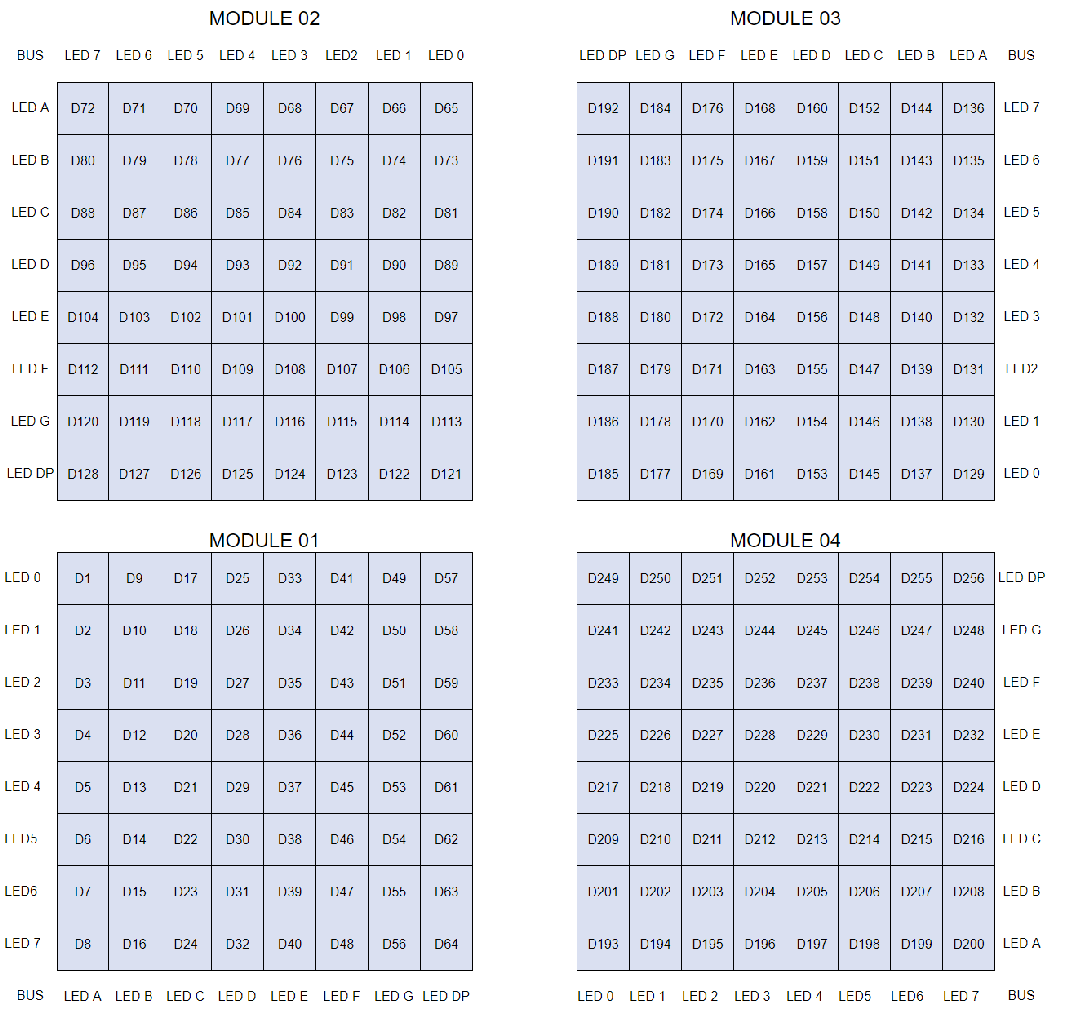
Step 12: Module Interconnections

Image 1 shows how the modules are connected. Most modules connect directly to the Arduino Nano.
The MAX7219 boards only connect to the NANO via module 01. The other modules are daisy chained together.
Each 8x8 LEDs matrix is then connected to a MAX7219 module.
The bulk of the wiring is the connections between the MAX7219 modules and the LED matrixes.
Keep the distance between the NANO and the 1st MAX7219 module and MAX7219 module to modules as short as possible. Also make sure you supply power to both ends of the daisy chained MAX7219s as most of the power is drawn by this part of the circuit.
Step 13: Construction Order of Build

Order of build presuming all prototyping and software changes are completed first.
Get vinyl transfer printed.
Get glass cut.
Cut MDF Sheets front and back.
Cut holes in front sheet for LEDs.
Paint MDF Sheets.
Cut holes for sensors in glass.
Stick Vinyl transfer to rear of glass.
Cut sensor holes in MDF front board.
Cut sensor module rebates in front board.
Cut MDF back board and make 4 access holes for sensor access.
Add melamine edge strips to MDF boards, white to front board and black to rear board.
Screw back MDF board to front MDF board.
Make Vero boards, 1 power board and 2 power distribution boards.
Modify 4 x MAX7219 boards and add wiring to LEDs.
Connect at MAX7219 end only for now.
Mount all modules and Vero boards on rear of MDF front board.
Construct all 4 LED matrixes on front MDF board and solder 256 LEDs.
Wire all Batt and Earth runs from power supply Vero board and power distribution boards.
Connect all power runs to all modules.
Connect all wiring to Nano, MAX7219 modules, RTC , Temp sensor, Touch Sensors and Buzzer.
Connect all wiring looms from modified MAX7219 boards to LED Matrixes as per wiring table.
Connect a PIR module remotely from the clock and connect the PIR connection.
Connect the 30 second sync to your Master Clock (if required).
Mount the Glass front display panel using the Chicago bolts also fixing the touch sensors at the same time.
Test.
Table 1 shows the very approximate build times for this clock and will vary depending on your skill level and also any specialist tools/working space you have to hand.
You can easily add another 40 hours prototyping and programming time to that list.
Attachments
Step 14: Construction Vinyl Sticker


Vinyl Sticker
Photo 1 The Vinyl sticker is designed in Inkscape.
Inkscape is professional quality vector graphics software which runs on Windows, Mac OS X and GNU/Linux. It is used by design professionals and hobbyists worldwide for creating a wide variety of graphics such as illustrations, icons, logos, diagrams, maps and web graphics.
Inkscape uses the W3C open standard SVG (Scalable Vector Graphics) as its native format, and is free and open-source software.
I downloaded the original Inkscape design by Wouter Devinck from his GitHub repository and then modified it in Inkscape to suit my design. I tried out many different versions on my miniature prototype before sending the final design off to be printed.
Don't forget to get the sticker reverse printed!
I used a company called Regal Signs & Graphics who supplied my sticker in black vinyl, reverse cut, lettering weeded out and supplied with an application tape all for around £27 inc vat.
Although they are quite local to me I paid a bit more and got my sticker delivered in a nice secure cardboard tube.
I had a few problems getting the design in the correct format for their machine but in the end I sent it from Illustrator in eps format the very helpful people at Regal Signs scaled it down to the correct size for me.
My Inkscape file can be downloaded here VINYL STICKER or from the image file at the top of the screen.
The Vinyl sticker came from Regal Signs with the letters weeded out so this saved me lots of time.
The sticker comes with a plastic tape over the front (glass) side and an application paper on the rear. Usually you peel the from side tape off apply the sticker and then remove the application paper. I decided to leave the application paper on as it acted as a diffuser for the LEDs. As I was leaving the application paper on I trimmed off the excess paper around the sticker before applying.
Photo 2 reverse side of sticker.
The sticker application was relatively easy. Just make sure you watch a few YouTube videos on Vinyl sticker application to glass before trying it yourself.
Glass
Photo 3
The clock uses 4mm float glass and has been cut to exactly 500mm x500mm. As the edges are exposed the edges have also been polished.
This was all done by my local glaziers for £20.
5mm holes were then drilled in the glass panel using a 5mm glass drill. Checkout YouTube videos on how to drill holes in glass.
I cleaned the glass first with acetone and made sure it was dust free (very important). I then put on some plastic gloves to make sure I did not get any fingerprints on the sticker.
I sprayed the glass with a very diluted soap and water mixture and then very slowly peeled back the plastic film from the sticker to reveal the front surface.
It is important to peel the film back slowly and at a very acute angle so the letters on the sticker stay connected to the transfer paper. Once the sticker is completely exposed apply it to the wet glass surface.
The water/soap mixture will allow you to move the sticker to the correct place on the glass. Next use a credit card and work away from the centre of the sticker to remove any air bubbles. Leave the sticker to dry overnight then from the back of the sticker cut away the vinyl over the 4 mounting holes in the glass.
Attachments

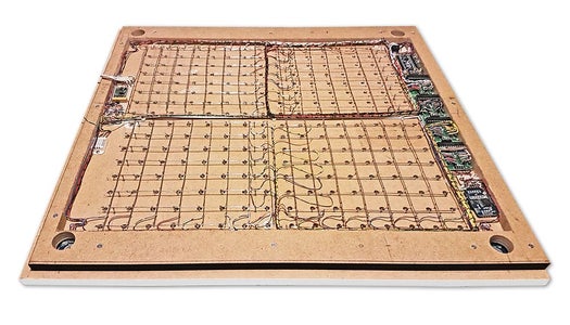
Step 15: Construction Main Boards Part 1


Main Boards
Animation 1 & Photo 1 The main board of the clock is made up of 2 sheets of 14mm MDF. The rear sheet is 10mm smaller than the top sheet on all sides apart from the top. The top has white edges while the back has black edges. When viewed on the wall the clock will then appear to be 14mm deep.
On the original Wouter Devinck Clock & the "Catalan" Pijuana version a single 18mm thick sheet of MDF is used with the back routed out to make space for the PCB and components. Using 2 sheets of MDF means the backboard can be simply cut out using a jigsaw rather than the time consuming and dusty routing. The top sheet is 503mm x 503mm to give a 1.5mm overlap around the glass. This will give the glass a bit of protection from knocks.
Photo 2 The backboard is cut out using a jigsaw and allows 14mm of component space.
The deepest PCB including components are the MAX 7219 modules that are 10mm deep. On completion the rear board is glued or screwed to the front board.
Front Board Construction
Photo 3 The front board holds the 256 LEDs that shine through 6.5mm holes and wider 18mm countersunk holes to illuminate individual letters and numbers on the display.
The board is marked up to show the drilling position of in the centre of each display character. Using a 500mm display I measured my vinyl sheet and the characters are 25mm apart starting 62.5mm from the edges. I drew these lines on the MDF, the intersections being the drilling points.
Photo 4 I used the top edge as the datum point I measured and marked each row from this point.
This was repeated for the vertical column using the left edge as the datum.
Photo 5 The intersections of the grid will be the centre point for the 6mm LED mounting holes and the 18mm countersunk holes.
Photo 6 & 7 Using an automatic centre punch ( use a nail or screw if you don't have one) I punched the 256 intersection points of the grid.
Photo 8 Using a drill bit to suite your LEDs (6mm in my case) and using the punched holes as a guide for the drill bit drill out all 256 LED mounting holes.
Photo 9 The next task is to drill the 256 18mm countersunk holes using a 20mm countersinking bit.
To keep the countersunk holes at a uniform depth and width I built a countersinking jig using an off cut of wood. To make the jig a hole is drilled in the wood off cut to just fit the silver rotating bezel of my drill chuck. Using a test piece of MDF the countersinking bit is then moved in and out of the chuck until a countersunk hole of the correct diameter is made when drilling through the hole upto the chuck in the off cut of wood. Once the correct distance is found the chuck is tightened and the main board is drilled 256 times by centring the hole in the wood over the existing 6mm holes then drilling down until the chuck bezel hits the hole in the countersinking jig.
Photo 10 Completed front board with 256 countersunk holes and 6mm holes for the LEDs.
Photo 11 The board is then rubbed down and primed using MDF primer and painted white so the countersunk holes reflect the light from the LEDs.
Photo 12 A black edge is painted around the outside edge to hide the board as the glass is 1mm shorter all round. This setback also helps the glass disappear from view on the final clock. Four 5mm holes are then drilled in the corners to take the Chicago Fasteners. The Chicago Fasteners hold the glass in place, hold the touch sensors and provide a touch sensitive pad on top of the glass. The fasteners have 3mm shafts and will have a small bit of rubber tape wrapped around the shafts to protect the glass.
Photo 3 Turn the board over and drill a rebate with a forstner bit to take the four touch sensors. This hole will be offset from the hole drilled in the previous step.
Step 16: Construction Touch Sensor Mounting


Photo 1 See cutaway section through mounting bolt below.
The touch sensor modules are fixed to the front panel using the glass mounting bolts. The mounting bolts then act as touch sensors.
A 5mm hole is drilled through the sensor pad on the module to allow the glass mounting bolt to pass through.
The sensor pad is insulated by the MDF panel and a plastic washer.
Photo 2 The touch pad on the sensor module has a 5mm mounting hole drill through the sensor.
Photo 3 Touch sensors in rebates behind rear panel. Holes drilled into rear panel allows access to the Chicago Fasteners that hold the sensors/glass front in place.
Photo 4 Clock front panel with touch plates.
Step 17: Electronic Components & Modules


Photo 1 Atmega 328 pin connections in case you want to prototype the circuit on an Arduino Uno.
Pin label numbers refer to Arduino IDE numbers.
Photo 2 Arduino Nano Pin Connections.
Photo 3 LEDs from Bright Components UK
5mm White Flat Top LEDs offering a pure and consistent colour with a wide angle ultra bright light output.
Colour : White
Quantity : 256
Lenses Type : Round Flat Top
Crystal ClearBrightness : 13000mcdForward
Voltage : 3.2v - 3.8v
Forward Current : 20mA (typical), 30mA (Max)
Viewing Angle : 120 degrees
Photo 3 DHT22 Temperature & Humidity Sensor
The DHT22 is a basic, low-cost digital temperature and humidity sensor. It uses a capacitive humidity sensor and a thermistor to measure the surrounding air,and sends out a digital signal on the data pin.
You can only get new data from it once every 2 seconds, so sensor readings can be up to 2 seconds old.
Simply connect the first pin on the left to 3-5V power, the second pin to your data input pin and the right most pin to ground.
Photo 4 To prevent the temperature of the inside clock case being measured the top and left side vent of the DH22 are covered over with tape. This also stops dust being drawn into the clock case.
Photo 5 View of the lower edge of the clock from the rear showing the air circulation vents.
The DHT22 is mounted with it's right open side mounted tight against the lower rear cover.
Two small holes are drilled in the lower edge of the rear MDF board to allow air from the room to circulate around the sensor.
Photo 6 & 7 Arduino NANO
Power
The Arduino Nano can be powered via the Mini-B USB connection, 6-20V unregulated external power supply (pin 30), or 5V regulated external power supply (pin 27). The power source is automatically selected to the highest voltage source.
Memory The ATmega328 has 32 KB, (also with 2 KB used for the bootloader. The ATmega328 has 2 KB of SRAM and 1 KB of EEPROM. Input and Output Each of the 14 digital pins on the Nano can be used as an input or output, using pinMode(), digitalWrite(), and digitalRead() functions. They operate at 5 volts. Each pin can provide or receive a maximum of 40 mA and has an internal pull-up resistor (disconnected by default) of 20-50 kOhms. In addition, some pins have specialized functions: Serial: 0 (RX) and 1 (TX). Used to receive (RX) and transmit (TX) TTL serial data. These pins are connected to the corresponding pins of the FTDI USB-to-TTL Serial chip.
External Interrupts: 2 and 3. These pins can be configured to trigger an interrupt on a low value, a rising or falling edge, or a change in value. See the attachInterrupt() function for details.
PWM: 3, 5, 6, 9, 10, and 11. Provide 8-bit PWM output with the analogWrite() function.
SPI: 10 (SS), 11 (MOSI), 12 (MISO), 13 (SCK). These pins support SPI communication, which, although provided by the underlying hardware, is not currently included in the Arduino language.
LED: 13. There is a built-in LED connected to digital pin 13. When the pin is HIGH value, the LED is on, when the pin is LOW, it's off.
The Nano has 8 analog inputs, each of which provide 10 bits of resolution (i.e. 1024 different values). By default they measure from ground to 5 volts, though is it possible to change the upper end of their range using the analogReference() function. Analog pins 6 and 7 cannot be used as digital pins. Additionally, some pins have specialized functionality: I2C: 4 (SDA) and 5 (SCL). Support I2C (TWI) communication using the Wire library (documentation on the Wiring website).
There are a couple of other pins on the board: AREF. Reference voltage for the analog inputs. Used with analogReference(). Reset. Bring this line LOW to reset the microcontroller. Typically used to add a reset button to shields which block the one on the board.
Communication The Arduino Nano has a number of facilities for communicating with a computer, another Arduino, or other microcontrollers. The ATmega328 provide UART TTL (5V) serial communication, which is available on digital pins 0 (RX) and 1 (TX). An FTDI FT232RL on the board channels this serial communication over USB and the FTDI drivers (included with the Arduino software) provide a virtual com port to software on the computer. The Arduino software includes a serial monitor which allows simple textual data to be sent to and from the Arduino board. The RX and TX LEDs on the board will flash when data is being transmitted via the FTDI chip and USB connection to the computer (but not for serial communication on pins 0 and 1). A SoftwareSerial library allows for serial communication on any of the Nano's digital pins. The ATmega328 also support I2C (TWI) and SPI communication. The Arduino software includes a Wire library to simplify use of the I2C bus. To use the SPI communication, please see ATmega328 datasheet.
Photo 8 TTP223 Touch Sensor Module
The Touch Sensor Module is bolted to the front panel using the glass mounting bolts. The bolt goes through a 5mm hole drilled in the middle of the sensor.
Note the mounting bolt is touched to trigger the sensor but is insulated from the sensor itself through plastic washers. Four of these modules are used in the clock one mounted on each corner of the glass.
Photo 9 TTP223 Touch Sensor Module schematic.
Note the LEDs are not required and are removed from the modules (just break them off) to save power.
DS3231 AT24C32 I2C Precision Real Time Clock Module
Photo 9 & 10 Show the schematic before and after the modification.
My clock uses a DS3231 AT24C32 I2C Precision Real Time Clock Module.
The module comes supplied with a Lithium-Ion rechargeable battery see diagram. I use a non rechargeable battery so have removed resistor R5 from the module as per photo10.
Photo 11 Shows the location of R5 on the DS3231 module.
Photo 12 Shows charging Resistor R5 removed.
Photo 13 MAX7219 Display PCB with LED Matrix in place.
Photo 14 MAX7219 Display PCB with LED Matrix removed ready for use in this clock.
MAX7219 LED current limiting
The max current through the LEDs is set by a single resistor R1 on the module. The value of resistor can be found from the table photo 15 .
The module comes with a 10K resistor preinstalled but this can be removed and a resister to match your LEDs current added in it's place. My LEDs Forward Voltage is 3.2v - 3.8v @ 20mA. They can handle 30mA max but for long LED life 20mA is best. I have used 22KΩ resistors which will limit the current to around 20mA when the light levels are at their peek.
See setting automatic brightness levels.
Photo 16 1088AS LED Dot Matrix display view of lower edge Pins 1 to 8 left to right.
This is used for prototyping and is not required in the final project.
Step 18: Electronic Components & Modules LDR


Photo 1 LDR
An LDR is used to sense the ambient light levels. The LDR is around 500Ω in bright light and 10MΩ in the dark.
Photo 2 The LDR is positioned underneath the clock on the rear MDF panel.
Next to the LDR is a hole to give access to the trimmer resister to calibrate the LED brightness control.
Step 19: Schematic

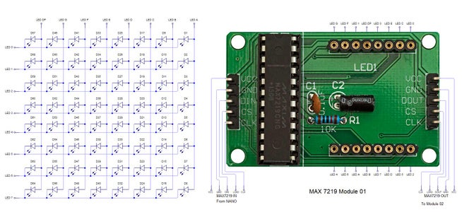
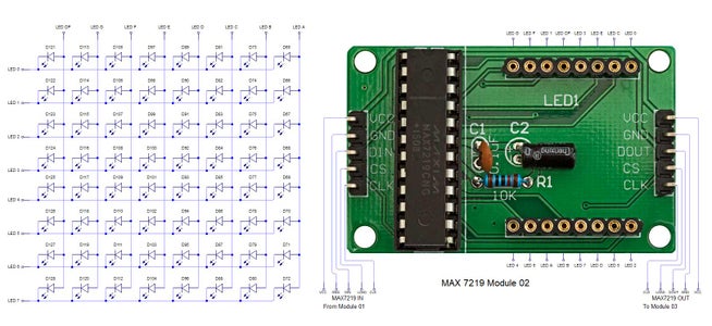
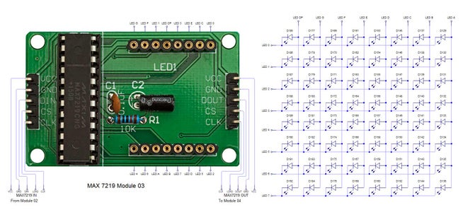
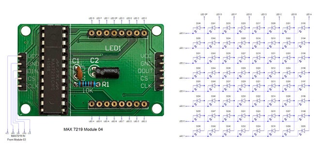

Photo 1 shows the connections to the Arduino Nano. Download the full size file from the zip file
Photos 2 to 5 show the 4 MAX7219 modules and the connected LED matrixes.
Photo 6 Note the LED display matrixes are rotated anti-clockwise 90 degrees from each other starting from display matrix 01.
Display Matrix 01 input is wired to the Arduino CLK,DIN and LOAD the output is taken to the input of Display matrix 02 etc etc.
Attachments
Step 20: Wiring Building the LED Matrixes
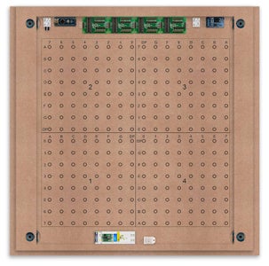


Photo 1 Module Locations
The module locations are shown below. The four sensors are located in the recesses on the main board behind the rear board. Holes are cut into the rear board to allow access for fit the Chicago Bolts/Sensor pads.
The four MAX7219 Display Modules are soldered together and are mounted in the centre top of the board. This keeps the data links between the boards as short as possible.
The Arduino Nano is mounted on the left of the MAX7219 Display Modules and the RTC on the right. The RTC battery holder on the base of the RTC module is recessed into the main board.
The Vero board containing the power module is located on the lower part of the board. There are two power distribution boards mounted on the top of the clock. The main 5v 2A feed cable is taken to both of these boards and power is then distributed to the other boards from these points.
The MAX7219 board power is fed from the left board and daisy chained through each board then taken out the forth board to ensure they are fed with 0v and 5v from both ends.
Photo 2 The LED locations are shown. The LED matrixes each contain 64 LEDs and are labelled 1 to 4.
These correspond to the 4 MAX 7219 modules mounted above numbered 1 to 4 left to right.
Photo 3 The LED Matrixes are built up off 2 types of BUS Bars per module. A Cathode Bus at 10mm high and an Anode BUS bar at 2mm high.
There are 8 Cathode and 8 Anode BUS Bars per module. Each module has 16 x 15mm panel pins hammered into the board in the position shown to support the 10mm high Cathode BUS.
Photo 4 The 15mm panel pins are hammered in 5mm (I used a 10mm piece of metal bar as a gauge) leaving 10mm as Cathode BUS bar support pins.
As shown below the pins correspond with the thick parts of the board not the recess for the LEDs on the front of the board.
Photo 5 0.9mm copper wire is then soldered to each pair of pins to form the Cathode BUS Bar.
Note the rotation of each module and also the modules are in reverse as it is the back of the board the LEDs are connected to.
Photo 6 The Anode BUS Bars are shown below in Red and are supported off each LED Anode about 2mm off the MDF board.
Photo 7 Both Cathode & Anode BUS Bar locations are shown below.
Each LED is connected to an Anode and Cathode of the Matrix.
Step 21: Wiring the LEDs


LEDs
Photo 1 Diagram showing Bus Bar layout with panel pins supporting the Cathode Bus. This module has horizontal Cathode and vertical Anode Bus Bars.
Photo 2 Close up section of Module wiring.
The Cathode BUS Bars run vertically and the Anode BUS Bars run horizontally on this module. The Anode & Cathode BUS Bars have an 8mm vertical separation.
Photo 3 LED Matrix Wiring Schedule
The LEDs are connected to the matrixes and MAX7219 modules from the rear. The LED positions will be reversed and of course rotated 90° relative to the next module. This makes it very complicated connecting the correct LEDs and Bus bars from the rear of the board. The table below shows the LED positions in the blue boxes with the BUS Bar matrix position in black around the outside as they appear from the back of the front MDF board.
Photo 4 The LEDs are bent in a jig to keep the position in the display constant and to speed up construction. Each LED has four bends two on each leg that's 1024 in total. The Cathode leg is bent 90° from the Anode.
Photo 5 Rear left of clock showing completed wiring
Photo 6 The Matrix grids are wired to the corresponding pins on the MAX7219 modules according to the layout table below.
There are 16 wires to each module.
Table 1 Module LED Matrix Wiring Colour Code is shown below.
Each Module has 16 wires connecting it to the LED Matrixes. I have used 50pr 0.5mm cable so the last 14pr colours are duplicated. On Mod 4 I went out of order and missed out the Sl/Vi at the start so have put it in at the end.
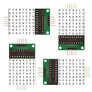
Step 22: Wiring Modifying the MAX7219 Modules


Photo 1 Before wires can be connected to the MAX 2917 modules they will need to be modified.
Photo 2 Two sets of 8 90° pin connectors will to be soldered to the lower edge of the existing LED matrix connector.
Photo 3 Modified MAX7219 module with 90° pin connectors soldered in place to the bottom of the old LED Matrix connectors.
Wires are taken away from these points to the LED matrix on the main MDF board as per the LED Matrix Wiring Colour Code table on the previous step.
Photo 4 Side view showing the pins soldered to the side of the old LED Matrix connector pins just above the PCB.
Note if your MAX7219 Module does not have surface mount components the 90° pin connectors may need to be trimmed back so they don't foul R1,C1 or C2.
MAX7219 LED current limiting
The max current through the LEDs is set by a single resistor R1 on the module. The value of resistor can be found from the table photo 5 . The module comes with a 10K resistor preinstalled but this can be removed and a resistor to match your LEDs current added in it's place.
My LEDs Forward Voltage is 3.2v - 3.8v @ 20mA. They can handle 30mA max but for long LED life 20mA is best. I have used 22KΩ resistors which will limit the current to around 20mA when the light levels are at their peek.
Note this sets the max current through your LEDs actual brightness is controlled by the LDR/software/ trimmer resistor and will usually be far less than this..
Step 23: Wring Mini USB Port

To allow adjustment/checking of light levels and programming of the clock a Mini USB socket is cut into the right hand side of the rear MDF sheet.
I have used a 25cm 90° Right angle Mini USB Male to Female Extension Cable and stripped back the insulation sleeve and shielding to expose the wires. This allows the cable to bend around the sharp angles and tight spaces of the enclosure.
Step 24: PIR Controlled Display Shutdown


The PIR when enabled on the Word Clock menu (bott left PIR On, bott right PIR Off) turns on the display when movement is detected in the room.
When no movement is detected the display turns off after a set period of time. When the PIR is enabled the displays shows "PIR ON" and when disabled (display always on) it shows "PIR OFF" Note when the PIR is not enabled the display is always On.
The PIR module is fitted remote from the clock in a modified chrome light switch box. The box is cut into a plasterboard wall and also contains a switch to turn the clock off. The module itself is very small and can be mounted in a tiny enclosure if you don't want it on show. It will not work behind glass so if you wanted to mount it on the clock a hole would need to cut in the glass. This is very easy to do with a large hole cutter.
Photo 1 A blank chrome switch plate and back box are used to house the power switch and PIR module.
Photo 2 Two holes are drilled in the blank switch plate for the power switch and PIR lens.
The hole are centre punched, pilot drilled and then drilled out just big enough for a step cutter to fit through. The hole for the PIR diffuser is cut just big enough for the lens to go through with a friction fit.
Photo 3 The completed switch plate. A bit of hot melt glue is used to make sure the module does not fall out.
Photo 4 The 12 volt supply +ve is terminated on the switch with the 0v terminated on the earth screw.
12 volts is then fed back upto the clock PSU Vero board from the other side of the switch and again the earth screw. 5 volts are fed from the clock PSU Vero board to supply the PIR module.
The 5 volts and PIR sensor wire to the clock terminate on PCB header sockets. These are is plugged into the PIR Module header pins. The sync cable is terminated on a header pins and connects to the Master Clock 30 second sync cable via a single header socket.
Photo 5 The PIR has 2 trimmer resistors for adjusting sensitivity and also length of time the PIR & display stay activated.
PIR On Off Control
The PIR is turned On & Off in Word clock mode by touching the bottom left sensor to turn the PIR on or by touching the right sensor to turn the PIR off. Note when the PIR is set to off the display stays on permanently. When you change the PIR setting the work "PIR ON" or "PIR OFF" is displayed for 5 seconds.
When initial power up the default is PIR off if you switch the PIR On straight away the display will go off as the PIR takes a minute or so to initialise before detecting movement.
Photo 6 & 7 "PIR ON" or "PIR OFF" are displayed for 5 seconds when PIR setting is changed.
Step 25: Doppler Radar Control Option


Added from v4.4 code onwards a Doppler Radar Module can be added.
Picture 1 Microwave Radar Sensor Module RCWL0516
The Doppler Radar when enabled on the Word Clock menu (bott left PIR On, bott right PIR Off) turns on the display when movement is detected in the room.
A check is made for motion on every quarter hour. When no movement is detected the display turns off until movement is detected again. When the PIR is enabled the displays shows "PIR ON" and when disabled (display always on) it shows "PIR OFF" Note when the PIR is not enabled the display is always On. Unlike PIR modules the Doppler Radar module can see through glass and plastic and is fixed into the case of the clock behind the glass and PVC sticker. The module has a range of around 5m or 16' 5".
Picture 2 Doppler Radar Module fixed inside the case. A hole is drilled in the front panel to allow the module to monitor the room.
Picture 3 Front panel showing hole through to the Doppler Radar module microwave sensor.
The module is hidden from view behind the PVC sticker and glass.
Step 26: Dust Seals


Photo 1 Dust Seals
To prevent ingress of dust two dust seals are fitted.
On the rear MDF board a 2mm soft foam rubber dust seal is fitted. When the clock is hung on it's hanging hooks the seal is under pressure and seals the back of the clock to the wall. The seal is self adhesive and is fitted with a 5mm gap to the edge of the rear MDF board.
Photo 2 On top of the front board to prevent dust getting under the glass a strip of self amalgamating rubber is fitted 5mm from the board edge.
To prevent the glass from cracking when the Chicago bolts are tightened 4 small square of rubber are also fitted around the holes in the glass. I punched holes for the Chicago Bolts in the rubber with a leather punch.
Photo 3 Dust seal in position on front board.
The clock is mounted on the wall using recessed wall hanging mounts. The fixing screwws on the wall should be just tight enough to put a bit of compression on the rear dust seal.
Step 27: Setting Automatic Brightness Levels

The clock automatically senses the ambient light and adjusts the LEDs accordingly.
When first installed the clock will need to be calibrated to the maximum light levels in it's actual location. Connect a mobile, laptop/tablet etc via a suitable cable to the mini USB port of the clock and open an app to monitor the serial port. I use Slick USB 2 Serial Terminal on my S7 via an OTG cable and USB to mini USB cable.
Photo 1 The clock will reboot and after the initial start screen you will see the following data updating down the screen.
You don't need to worry about lightReading or constrained lightReading+hyster just light reading, and bright.
With the clock in position and the ambient light at it's maximum levels carefully insert a flat bladed jewellers screwdriver into the access hole just to the right of the light sensor. Turn the screwdriver slowly until the light reading = 600 (or your level set in brightness.cpp) and bright = 15. Your clock will now go to max brightness when the ambient light is at it's maximum. If you turn the screwdriver too far the light reading will go over 600 but the bright reading will not increase.
If you want the clock to be dimmer right across the range of ambient light levels adjust the light reading to a level less than 600 at max ambient light levels.
Note when bright=15 this will output the max current to the LEDs. The max current is set by R1( RSET) on the MAX7219 module and this should be chosen for your type of LED used in the display.
Step 28: Setting the Clock

The clock is set in the digital clock mode by touching the bottom left sensor.
The hour digits will now flash twice a second to indicate the clock is in time setting mode.
In this mode the sensors have the following functions.
Top right - steps the hours or mins digits up
Top left- steps the hours or mins digits down
Bottom left 1sr press - enters the time setting mode selecting hours digits
Bottom left 2nd press -selects the mins digits for changing
Bottom left 3rd press -exits time setting mode and sets the time
Bottom right - resets the seconds to 00
Step 29: Synchronisation

If you have connected a 30 second master clock sync cable then the clock will jump back or forward to 30 seconds when out of time setting mode. If you don't have a Master Clock to sync to then the clock will fall back on the on board temperature compensated real time clock which in itself is a very precise quartz clock.
Just reset the seconds roughly in sync to the seconds (within 10 seconds either way) and wait for the clock to sync once out of time setting mode.
Animation 1 The animated loop below shows the Word Clock is running fast by several seconds. A synchronisation pulse is received from the Master Clock every 30 seconds on the minute and half minute synchronising the clock on 30 seconds.
The clock will ignore the 30 second synchronisation pulse from the Master Clock at 0 seconds. Note from v3.3 clock synchronisation only happens when the Word Clock is 20 seconds past and 20 seconds to a minute. In normal operation the sync pulse corrects the clock to within a fraction of a second so you will see the word "SYNC" appear with no visible correction to the seconds.
Note the synchronisation pulse is received every 30 seconds but the clock will ignore pulses at 0 seconds.
Step 30: Software & Making Changes


The software can be downloaded from the file above and contains the following modules.
Program Files Modules
Brett_wordclock_v4_3.ino Main program, latest update includes shortened code saving 10% in size.
Thanks to srdevil for providing the updated code for this seconds display.
brightness.cpp/.h Brightness autoadjustment
character.cpp/.h Character (digit) definitions
credits.cpp/.h Ending Credits
display.cpp/.h Display & LED functions
life.cpp/.h Game of Life
serial.cpp/.h Serial port setup menu
simon.cpp/.h Simon Says game
temphum.cpp/.h Temperature & Humidity displa
tetris.cpp/.h Tetris game
time.cpp/.h Wordclock, digital clock
timeanalog.cpp/.h Analogue clock
touchbuttons.cpp/.h Touch buttons, mode switching
Third party libraries:
Chronodot.cpp/.h Chronodot library (for DS3231)
DHT.cpp/.h Temperature sensor library (for DHT22)
LedControl.cpp/.h LedControl library (for MAX7219)
stc.cpp/.h/platform.h Simple Tetris Clone library
pitches.h Note frequencies from the Arduino webpage
When you want to make changes to my code you can compare my code to the "Catalan Code" to make it easier to understand what changes you need to make. I have added //Brett to my code to highlight my changes.
Changing the code.
If like me you are not very good at coding just play around with the code to get an understanding of how it works.
I just save a different version each time I make even a tiny change. This way if I mess up I can go back a version and start again.
If you are keeping my linear seconds display update the version number on the display so you know what version you are trying out each time. This is done in the module credit.h around line 47.
It would take far too long to explain all the code but here is a very brief guide on how to change the words and when they are displayed.
Photo 1 The WORDS are set in time.h
On line 52 we have
const byte w_the[3] PROGMEM = { 0, 0, 3 };
The word "THE" is described in this line with the LED location in the curly brackets "{ 0, 0, 3 }"
This is the co-ordinate of the LEDs we are gong to light when we call "w_the"
The LED matrix numbers starts top left and start from 0 so "{ 0, 0, 3 }" is the first LED across and down the 3 just means the 3 LEDs across including this one will light. As the letters THE are in this position the word "THE" is displayed.
Similarly the word "TIME" would be lit by lighting the four LEDs here { 0, 4, 4 } or row 0, 5th LED along and light 4 LEDs (remember to count from 0).
Working you way down the page shows the position of all the words.
Photo 2 Controlling when words are lit
This happens in the module time.cpp
Here you just make a list of rules to tell the clock what words to light at certain times.
Photo 2 shows part of the code starting with line 695
At midnight we want to make the clock say "THE TIME IS TWELVE OCLOCK AT NIGHT"
Midnight is 00 00
"THE TIME IS" is always displayed from lines 687
So we add the rules if minutes are 0, then if hours are 0 show the word for hours "TWELVE" and the word "OCLOCK" the word "AT" and the word "NIGHT"
If you follow the code down all the possible time combinations are covered.
Note v4.5 added includes shortened code saving 10% in size.
Thanks to srdevil for providing this updated code for the seconds display.
Also includes code for both PIR and Doppler Radar Module
Analogue Clock Code Change - increase in time definition
On the comments section srdevil has posted some code changes. His comment and can be seen below.
I have not had time to test the code but have included it below if you want to try it out.
" If the time is 18:00, it points up (long leg) and down (short leg). But when the time is 18:59, it still points totally down (short leg) so it looks like the time is 17:59 on a normal clock. My brother change the code so that if it is >HH:15 the small pointer moves already to the next number. As of this we also increased the resolution in the part between >HH:15 -
Code on the comments section or can be seen here http://home.btconnect.com/brettoliver1/Word_Clock/Word_Clock.htm#analogeclock
Attachments
Step 31: V4.6 Adding Touch Sensor Enable/Disable Switch


Photo 1
Touch Sensors Enable/Disable Switch (added from v4.6)
This miniature slide switch is glued to the top right corner of the clock case out of sight. The switch enables/disables the touch sensors. This prevents people from messing around with the clock. A 10K Ω resistor is soldered from Eth to D12 on the Nano. The switch is then wired from 5v to D12.
Photo 2
Shows touch enable/disable schematic


![Tim's Mechanical Spider Leg [LU9685-20CU]](https://content.instructables.com/FFB/5R4I/LVKZ6G6R/FFB5R4ILVKZ6G6R.png?auto=webp&crop=1.2%3A1&frame=1&width=306)


