

Introduction: Control an LED Over the Internet Via Arduino With Teleduino


This process is made really simple using the Teleduino sketch for your ethernet enabled Arduino. Haven't heard of Teleduino? That's cool, you may want to take a look at Arduino Control via a Web Service with Teleduino to get yourself started.
This tutorial will guide you through the process of attaching an LED to your Arduino, and provide some example Teleduino API calls to:
- Define the pin mode of a pin
- Turn on the LED
- Turn off the LED
- Set the brightness of the LED (using one of the PWM supported pins on the Arduino)
If you get stuck on any of the steps, or if you feel that there is a step that could be explained better, please leave a comment so that we can improve things.
Let's begin!
Step 1: Prepare an LED
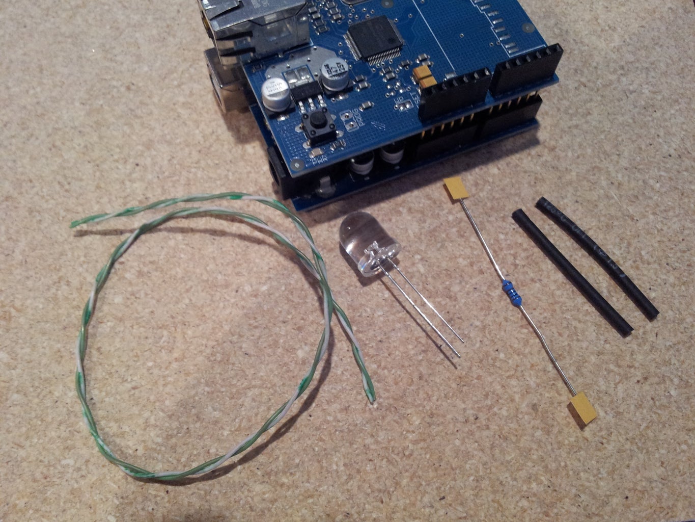


Parts needed:
- An LED (we decided to use a 10mm white LED because they look neat)
- A 1K Resistor (or similar)
- Some hookup wire (we chose to use some single strand ethernet cable because it's cheap, and connects well to the Arduino pin sockets)
- Some heatshrink (optional, but makes it look nice and tidy)
Steps:
- Take the LED and shorten the lead on the flat-edge side (the shortest lead).
- Shorten one of the leads on the resistor.
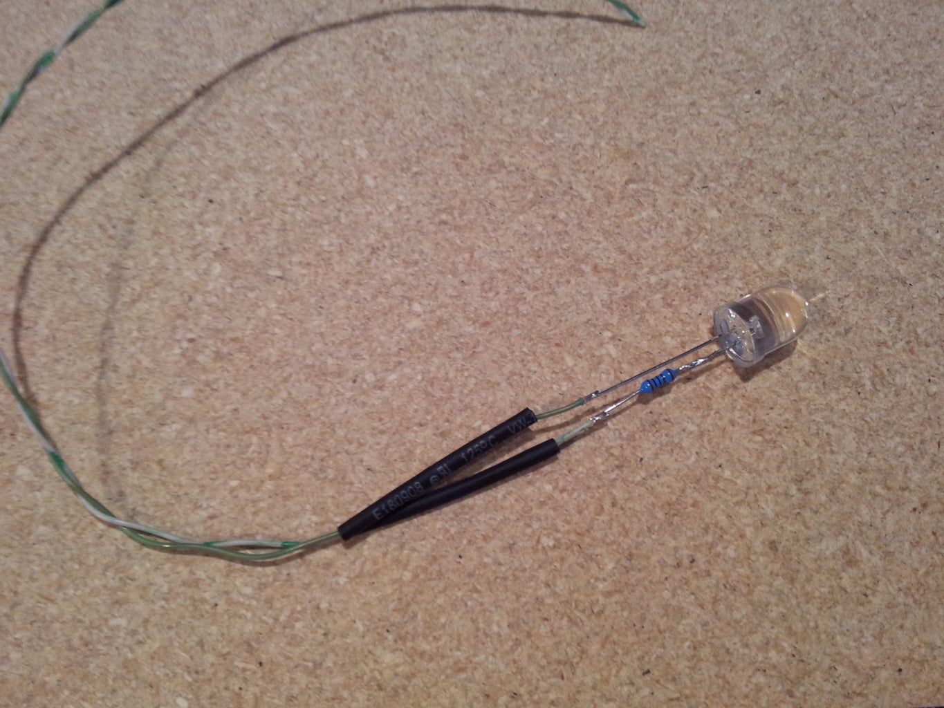
- Solder the short lead of the resistor to the short lead of the LED.
- Shorten the other lead on the resistor so that it's the same length as the remainder lead on the LED.
- Solder the hookup wire to the two leads, and apply heatshrink. Take note of which lead is soldered to the resistor (we chose the white wire for this).
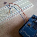
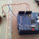
- Strip the other end of the hookup wires and connect to the Arduino. The white wire (the wire connected to the resistor) connects to a GND pin, and the other (our green wire) connects to a digital pin (we chose pin 3 because it also supports PWM).
Awesome!
Step 2: Control LED Via the Teleduino API


Here are some example API calls that you can use to control your LED. You need to replace {key} with the unique API key you obtained when you completed the instructable Arduino Control via a Web Service with Teleduino. Just chuck the URLs into your browser's address bar and you should see some magic happen on that LED.
Define the pin mode of digital pin 3 (Must be done once per boot prior to setting digital outputs. 'pin=3' mean pin 3, 'mode=1' means OUTPUT):
http://us01.proxy.teleduino.org/api/1.0/328.php?k={key}&r=definePinMode&pin=3&mode=1
Set the output of digital pin 3 to HIGH ('pin=3' means pin 3, 'output=1' means HIGH):
http://us01.proxy.teleduino.org/api/1.0/328.php?k={key}&r=setDigitalOutput&pin=3&output=1
Set the output of digital pin 3 to LOW ('pin=3' means pin 3, 'output=0' means LOW):
http://us01.proxy.teleduino.org/api/1.0/328.php?k={key}&r=setDigitalOutput&pin=3&output=0
Toggle the output of digital pin 3 ('pin=3' means pin 3, 'output=2' means toggle):
http://us01.proxy.teleduino.org/api/1.0/328.php?k={key}&r=setDigitalOutput&pin=3&output=2
Set the PWM value of pin 3 to 32 (LED will glow dull. 'pin=3' means pin 3, 'output=32' means PWM value):
http://us01.proxy.teleduino.org/api/1.0/328.php?k={key}&r=setPwmOutput&pin=3&output=32
Set the PWM value of pin 3 to 255 (LED will glow bright. 'pin=3' means pin 3, 'output=255' means PWM value):
http://us01.proxy.teleduino.org/api/1.0/328.php?k={key}&r=setPwmOutput&pin=3&output=255
Pretty neat, huh?
Step 3: Further Reading
Controlling an LED is just a very simple example of what can be achieved by using the Teleduino Arduino library/sketch.
To view the full API reference manual, take a look at http://www.teleduino.org/rtfm/api/328.php.
Have fun!

Participated in the
Arduino Challenge


