

Introduction: Digital Mirror Device (Macroscale Model)


My last project focused on building a large-scale version of a CD player. With the same spirit, I decided to build a scaled up version of a Digital Micromirror Device (DMD). The inspiration for this project came from Ben Krasnow's Applied Science channel: How DLPs Work. In this video, Ben provides a great explanation for how Digital Light Projectors work and builds a demonstrator. He mentions the possibility of building a mirror array with solenoids to flip each mirror individually. That idea was always interesting to me, and so I finally decided to try it out.
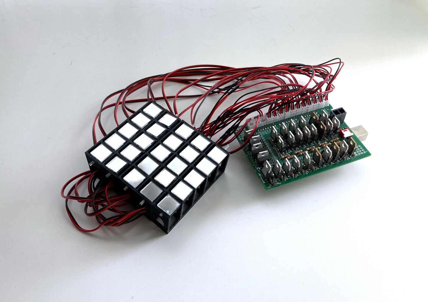
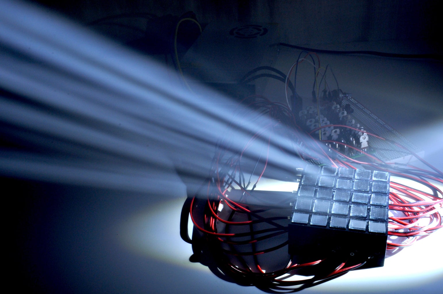
DMDs usually consist of several hundred thousand mirrors! The device I built has only 25 mirrors... Each mirror can flip between two states using a push-pull solenoid. The pattern on the array is controlled by an Arduino.
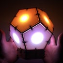
This project is also related to the artwork of Daniel Rozin. He builds "mechanical mirrors" out of objects arranged in a 2D array that flip to form an image. Often the array displays an image of the observer in front of it, similar to a mirror.
Here is a "lo-fi" version of the same concept.
Supplies

0.5 inch square mirrors - Amazon
Mini Push Pull Type Solenoid Electromagnet Linear Motion Rod - Ebay
TIP120 NPN 5 A 60 V Silicon Epitaxial Power Transistor - Amazon
5V 40A power supply - Amazon
Power switch outlet - Amazon
Power switch PCB - Mouser
Power cable to PCB - Mouser
Power cable jack on PCB - Mouser
Arduino Mega - Arduino
Toothpicks
Super glue
Step 1: Mechanical Design


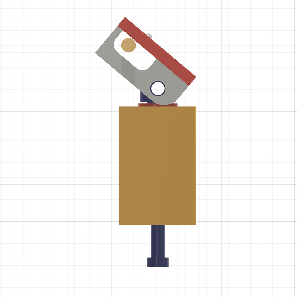


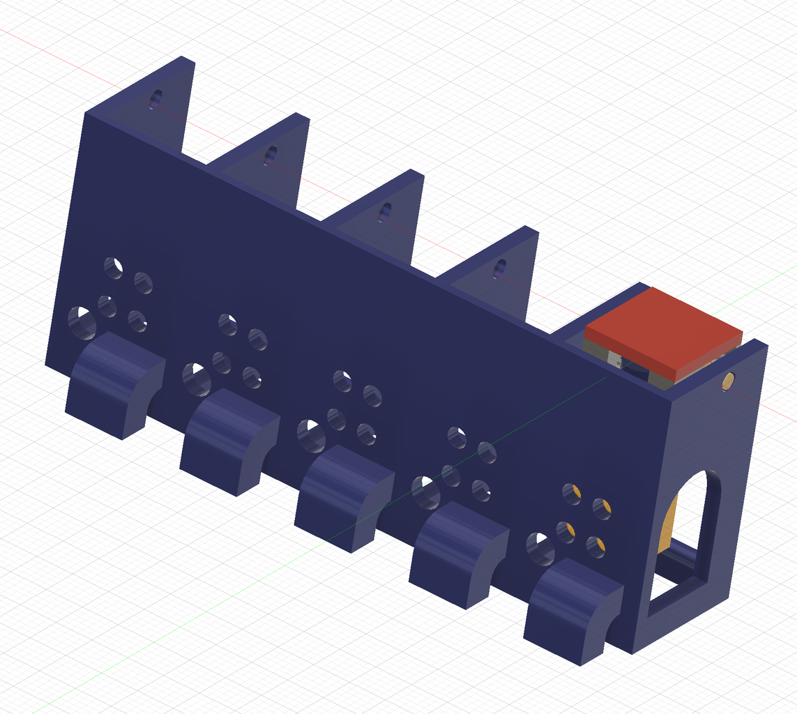


I decided to make a 5x5 mirror array. All the mechanical design was done using Fusion 360.
The primary function to figure out for this device was the mirror switch. I found small solenoid push-pull rods on Ebay and decided to try working with them. My designs started small with only a single mirror switch. After about four or five prototypes, I came up with a design that worked pretty well. I scaled up the design to include all the mirrors in a single row. The grid is formed by locking in each row together.
To build the device, you will need to 3D print the attached STL files.


Step 2: Electrical Design


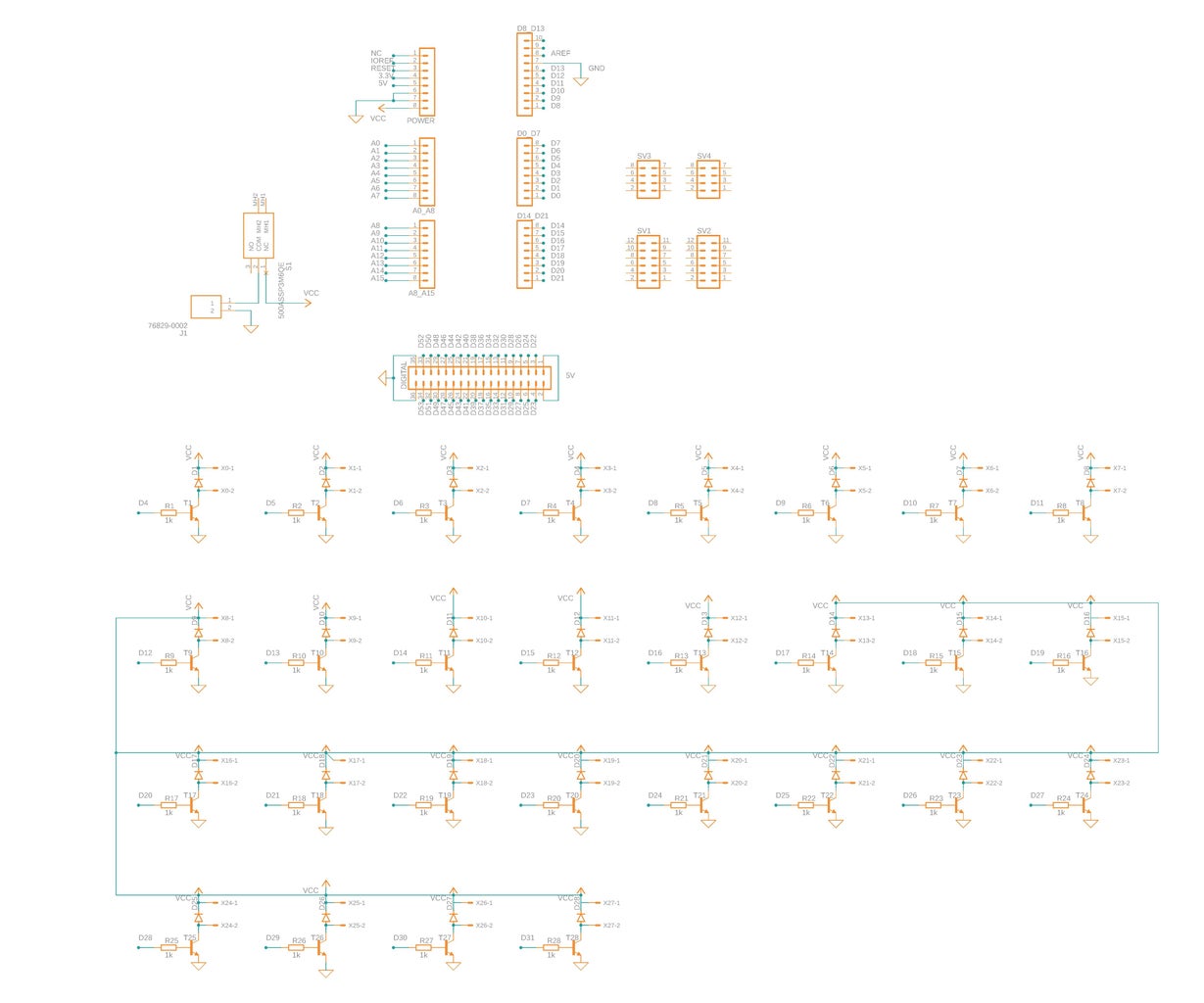


The electrical design for the project is pretty straightforward. A power transistor is used as an electrical switch for the solenoid with an Arduino digital pin at the base. The bigger issue is the number of collections and transistors. Instead of working with a prototype board, I decided to design an Arduino shield using Fusion360.
The shield itself is actually pretty useful for any Arduino project that requires a lot of high-power transistors in saturation (i.e. projects that require switch a lot of high-power components on and off).
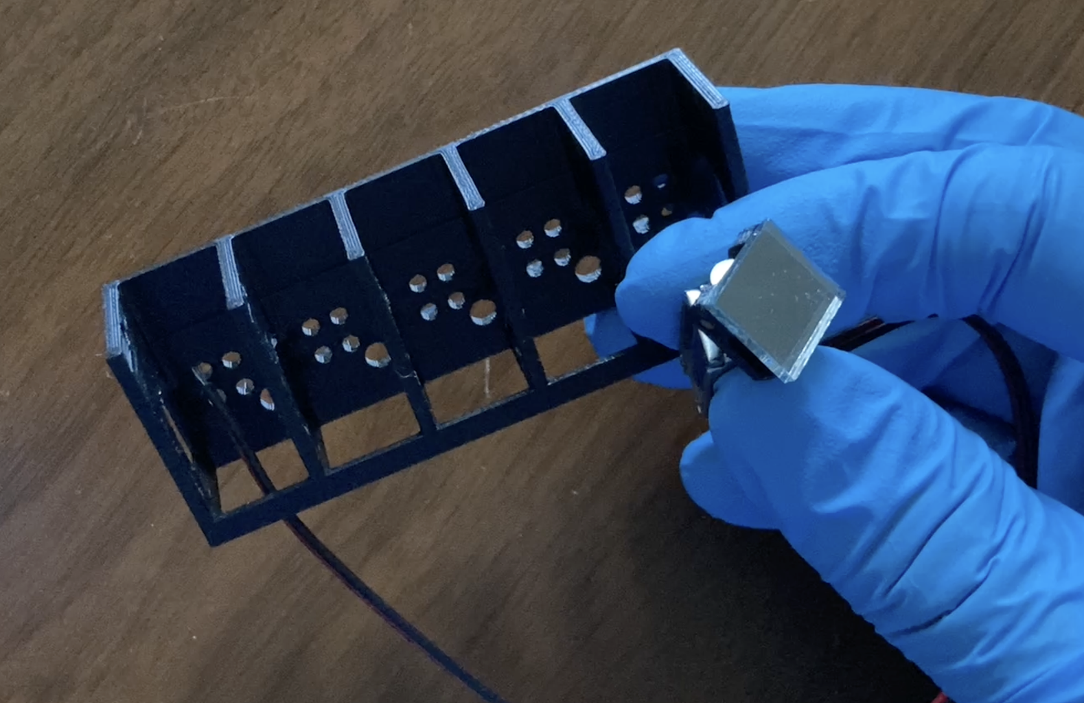
Step 3: Mirror Array Assembly


The mirror is attached to the solenoid with the 3D printed mount (03mirror_mount.stl). A toothpick was inserted to attach the solenoid and 3D-printed mount. I then glued the toothpick in place, making sure that the mount could stick rotate. Finally, the mirror was glued on top of the mount. I repeated the process for all 25 mirrors.
Step 4: Mirror Holder Assembly


I attached the solenoids onto the mount using a few Allen bolts. Each row was then connected using the hook at the base of the rows. The cables are guided through the back of the mount, but it is quite a tight fit!
Step 5: PCB Assembly


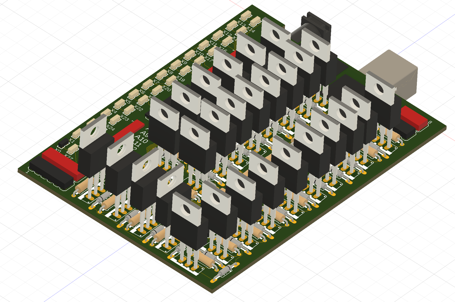


I first tested one row of the device with a prototype board. One major issue with the design is the amount of current that is drawn by the solenoids. I bought a 40A supply to deal with the power demands. I think the circuit could be improved to lower the current demands, but I decided to just move forward with a simple design.
Once I received the PCB, I populated it with all the components. The shield then fits on top of an Arduino Mega. The device seemed to be working well, but then there was ... smoke. Investigating the PCB I noticed a burnt trace. I realized that the amount of current going through this trace was way too high for the thickness I set. I patched up the board with a lower gauge wire. I updated the trace thickness in the attached Fusion360 file, but it has not been tested.
Attachments

Step 6: Programming
The program moves through a sequence of mirror array displays. I chose a couple simple sequences to display the concept. To convert the display into the mirror position, I created a Matlab script (attached). The Arduino code then uploads the sequence so that the mirrors can flip through on and off according to the current frame in the sequence.
I'm happy that the code works and displays some cool patterns, but it may be more interesting for the device to be interactive. There are open pins on the Arduino Mega for some distance sensors for example. For now, I've just added a potentiometer to adjust the speed or buttons to manual select a pattern.
One major issue with the mirror array is the slight angle difference on each mirror. When light reflects off the DMD, each mirror directs the light at a slightly different angle. The error appears worse the farther from the DMD the screen is. The problem could be mitigated by using a lens or concave mirror (like in the Applied Science video).

Runner Up in the
Make Some Noise Contest


![Tim's Mechanical Spider Leg [LU9685-20CU]](https://content.instructables.com/FFB/5R4I/LVKZ6G6R/FFB5R4ILVKZ6G6R.png?auto=webp&crop=1.2%3A1&frame=1&width=306)


