

Introduction: Floating Display Clock


This is a clock with a floating display based on Aerial Imaging by Retro-Reflection (AIRR). The numbers from individual LED panels are projected using a beamsplitter and a retroreflective foil. For the observer the numbers seem to float in the air a few centimeters in front of the clock's screen. To enhance the 3D impression I added servo motors to the LED panels so that they can be tilted. This makes the digits seemingly rotate in and out of plane.
Supplies
Materials
- Wemos D1 mini ESP8266
- PCA9685 16Ch Servo Driver board
- 4pcs SG90 micro servo
- 4pcs 8x8HD DigiDot LED panel (ebay.de)
- beampslitter glass 207x137mm (ebay.de)
- Orafol ORALITE Superlens 3000 DIN A4 (reflexfolie.de)
Tools
- 3D printer
- soldering iron
Step 1: Retroreflective Floating Displays


Aerial Imaging by Retro-Reflection (AIRR) is a simple technique to create 3D floating displays. As shown in the picture above you can create an image of a light source in midair with a beamsplitter and a retroreflector. To learn more about floating displays there is a great website by Yutaka Tokuda from Tokyo University.
The beamsplitter can just be a simple piece of glass or acrylic but there are also specially coated glasses. Normal glass has a reflectivity of only about 4%. To achieve maximum brightness in the floating display you can easily calculate that the optimal reflectivity would be 50%. I used a beamsplitter glass with 70% transmission and 30% reflection made for teleprompters.
For a retroreflector the reflected light is always parallel to the incoming light. To build a floating display you need an array of retroreflectors which exist in the form of retroreflective films. These are either based on glass beads or microprisms. The materials are commonly used for traffic signs or safety workwear. I tested several different retroreflective films 3M 580E, 3M 9925, Orafol ORALITE Superlens 3000 and found that the letter gives the best overall performance in terms of brightness and contrast.
Step 2: 3D Printing

The housing was designed in Fusion360 and 3D printed from black PLA to avoid reflections. It is quite big and uses a lot of filament but can be printed without supports. I experienced quite a bit of warping even though the part with printed with brim.
I also 3D printed small connectors to attach the LED panels to the servos.
All stl files can be found on my GitHub.
Step 3: Electronics

The clock uses a Wemos D1 mini ESP8266 board which controls the LED panels and the servos. The servos are attached to a PCA9685 board. The LED panels consist of a high-density 8x8 array of SK6812 LEDs. There is one panel per digit. To power everything I used a USB-C breakout board but it turns out that can also power everything directly from the micro-USB port of the Wemos board. When I run the LED panels with reduced brightness the ahole clock consumes less than 500mA.
Step 4: Assembly


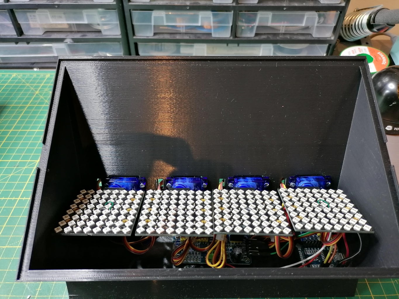

- solder ~5cm cables to LED panels. Fist panel gets cable with "Dupont" connectors
- attach servos to housing with included screws
- mount PCA9685 board into housing with M2x4 screws
- mount Wemos board into housing and fix with hotglue
- wire electronics according to schematics above
The code should be uploaded before attaching the LED panels in order to move the servos to the zero position
Step 5: Upload Code
The code can be found on my GitHub and can be uploaded with the Arduino IDE. The following libraries need to be installed first.
- Adafruit_GFX
- FastLED
- FastLED_NeoMatrix
- Adafruit_PWMServoDriver
The clock connects to your local WiFi and fetches time from an NTP server. You have to enter the NTP server and timezone in the clock.h file. After uploading the clock will open a WiFI AP called "FloatingClockAP" which lets you enter your WiFi credentails. The clock will then restart and try to connect to your WiFi. Before connecting the clock will zero all servos so you can disconnect if from power and attach the 3D printed servo connectors. Before attaching the LED panels you can check the correct min/max position using the testServos() function. I adjusted the values so that the panels are tilted about -20° in the minimum postion and +90° in the maximum position. The SERVOMIN and SERVOMAX values may need to be adjusted depending on the exact servo type.
When a certain digit on the clock changes the panel will tilt to the 90° position change the number and then tilt back. This gives the impression that the digit is rotating towars the viewer. In addition the color of the digits changes every minute.
Step 6: Finished Clock


The 3D effect of the display is much more impressive in reality than on the video. I also recorded a video with a cheap stereo camera. With the cross-eyed viewing technique you get a better impression of the 3D nature of the display.

Participated in the
For the Home Contest


