

Introduction: How to Make Arduino Gate System


Hey readers, welcome back to my one another interesting instructable.
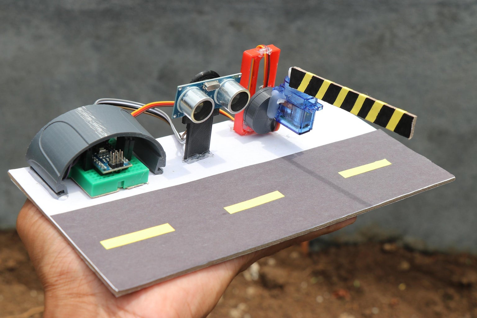
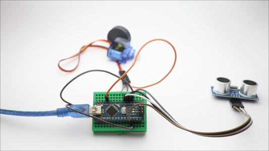
In this project, i will show you how you can make a simple Arduino-based gate system using an Arduino Nano, ultrasonic sensor, micro servo, and some jumper wires.
Let me quickly define you what this project is all about
This project aims to demonstrate a basic application of sensor-based automation, where the gate will open automatically when someone approaches it and close when the person moves away.
You can easily build this project, to make it makable for everyone I have explained the circuit diagram, explained the working of the code, and provide step-by-step instructions to build the project on a piece of cardboard
Note that I have also given a working video at the end of this instructable
Supplies
To build the Arduino gate system, you will need the following components:
I will provide short info about the role of each component
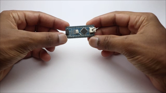
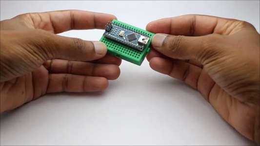
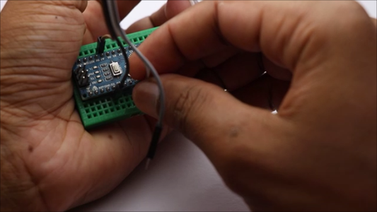
Arduino Nano
The brain of the system that is responsible for processing data and controlling the micro servo.
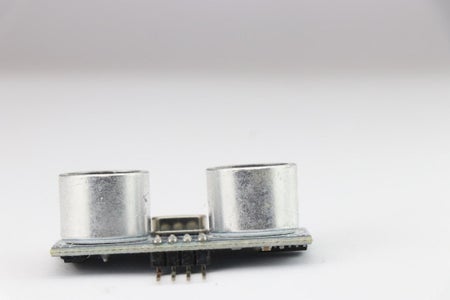
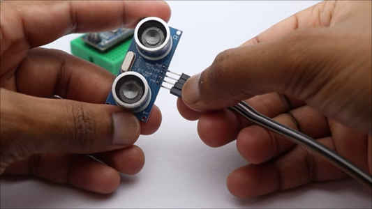
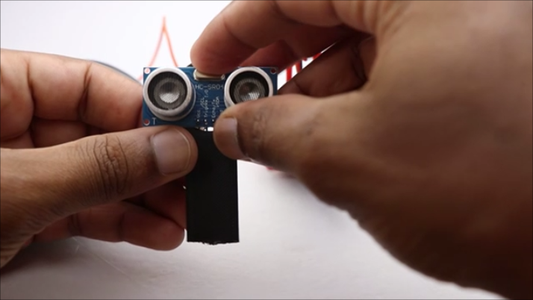
Ultrasonic Sensor (HC-SR04)
Used to detect the presence of an object or person near the gate.
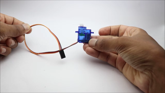
Micro Servo Motor
Responsible for controlling the gate's movement.
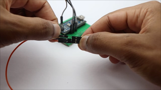
Jumper Wires
To establish electrical connections between the components.
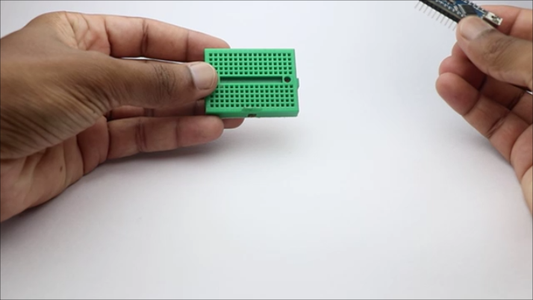
Mini Breadboard
To make jumper connections
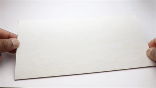
Piece of Cardboard
To create a simple base for mounting the components.
How ultrasonic sensor works?
Ultrasonic sensors use sound waves to detect the distance of objects in their surroundings.
The sensor emits high-frequency sound waves (typically above the range of human hearing), which then bounce off nearby objects and return to the sensor.
By measuring the time it takes for the sound waves to travel to the object and back, the sensor can calculate the distance between itself and the object.
These sensors consist of two main components: a transmitter and a receiver. The transmitter generates the ultrasonic sound waves, while the receiver picks up the echoed signals.
The time taken for the sound waves to travel back is proportional to the distance of the object from the sensor.
How Micro servo works?
Micro servos are small devices commonly used in robotics and other projects where precise control of angular position is required.
They are essentially compact motors integrated with a gearbox and a control circuit.
The servo motor inside the casing rotates to a specific angle based on the electrical signal it receives. It consists of three wires: power (Vcc), ground (GND), and signal (control).
The servo's control wire is connected to a PWM (Pulse Width Modulation) pin on the Arduino. The Arduino sends a series of PWM signals to the servo, with the width of the pulse determining the desired position of the servo motor.
By adjusting the pulse width, you can control the servo to rotate to different angles within its range, usually 0 to 180 degrees.
Step 1: Circuit Diagram
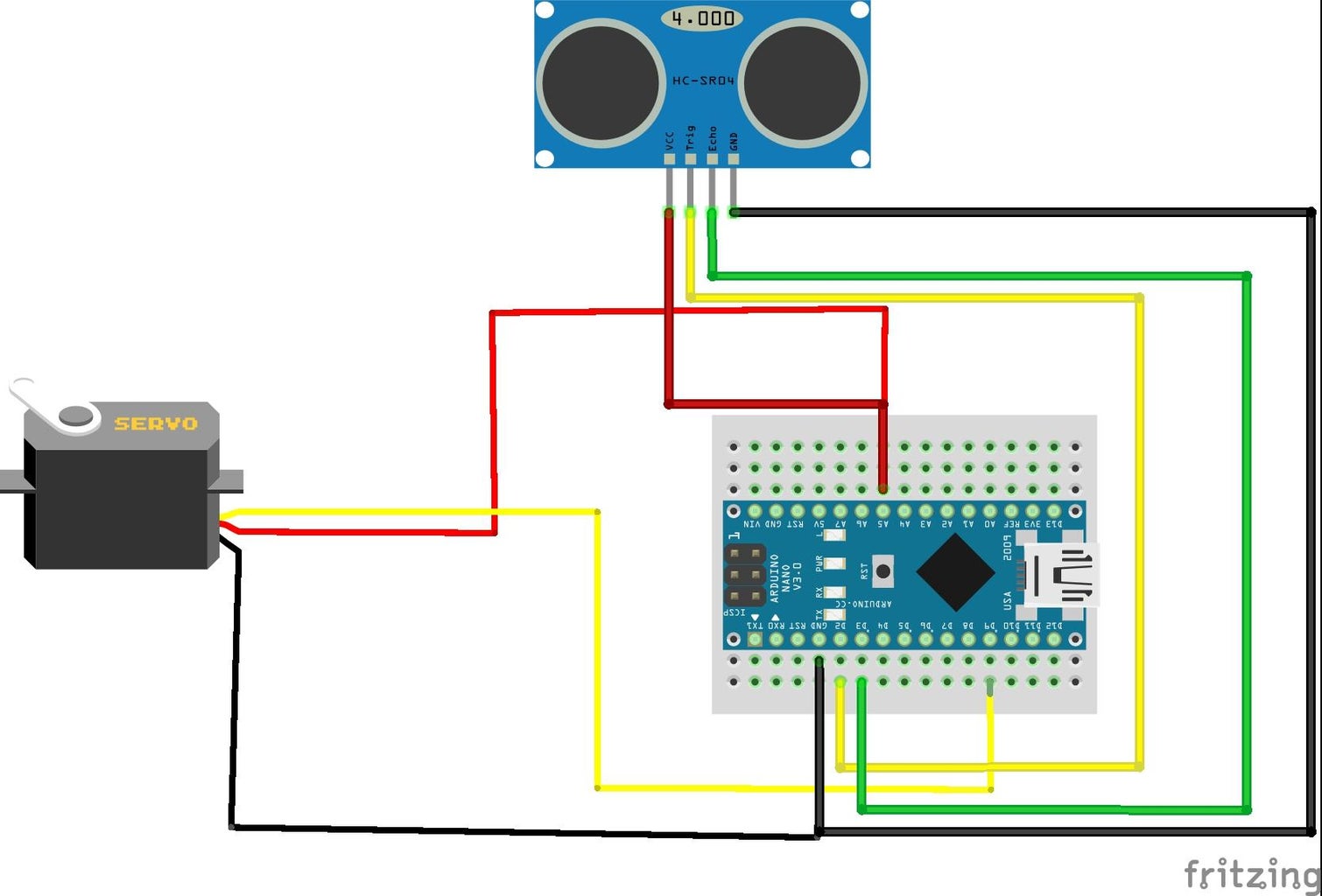


I will give you a simple Explanation of the Circuit Diagram, just have a look at the diagram once hold your jumpers and start building the circuit!
The circuit diagram for the Arduino gate system is straightforward. Follow these connections:
Connect the VCC pin of the ultrasonic sensor to the 5V pin on the Arduino Nano.
GND pin of the ultrasonic sensor to the GND pin on the Arduino Nano.
Trig pin of the ultrasonic sensor to digital pin D2 on the Arduino Nano.
Echo pin of the ultrasonic sensor to digital pin D3 on the Arduino Nano.
Connect the signal (control) pin of the micro servo to digital pin D9 on the Arduino Nano.
Connect the VCC and GND pins of the micro servo to the 5V and GND pins on the Arduino Nano, respectively.
Want to simplify this circuit? Buy PCBs for your electronic projects from PCBWay.
Why them? They have provided me with the best PCB and The quality is just amazing compared to other providers in the market
A revolutionary solution that combines the best of both rigid and flexible circuitry to elevate your electronic projects to new heights.
With their expertise in advanced manufacturing techniques, they offer a seamless integration of rigid and flexible components, ensuring enhanced reliability, durability, and space-saving benefits
Check Here for Rigid-flex Pcbs
I bet you have not seen anywhere such assembly capabilities, Check here to know their best in-industry assembly techniques
Step 2: Arduino Code
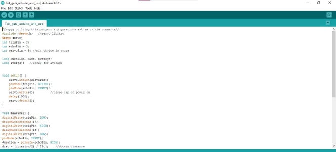
Let me explain the code so that you could make any changes if you are willing to
These are the variables used throughout the code, Here's what each variable means:
servo: A Servo object that will be used to control the servo motor.
trigPin and echoPin: These are the pins connected to the ultrasonic sensor for triggering and receiving the echo signal, respectively.
servoPin: The pin to which the signal wire of the servo motor is connected.
duration: The time taken for the ultrasonic pulse to travel back and forth.
dist: The calculated distance from the ultrasonic sensor to the object (hand).
average: A variable to store the average distance obtained from multiple measurements.
aver[ ]: An array to store three distance measurements for calculating the average.
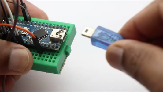
How to upload the code to Nano?
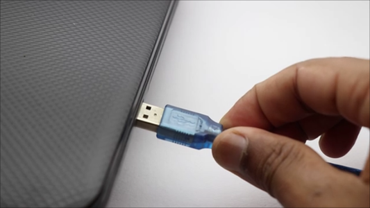
Connect your Arduino Nano to your computer using a USB cable.
Open the Arduino IDE on your computer, In the Arduino IDE, go to "Tools" in the top menu and select the following options, Board-> Arduino Nano, Processor-> ATmega328P (Old Bootloader), Port: Select the COM port that corresponds to your Arduino Nano.
If you're not sure which port to choose, check the ports before and after connecting the Nano, and the new port that appears should be your Nano.
- Copy the entire code you provided in your question and Paste the code into the new sketch.
- Click the "Upload" button (the right arrow icon) in the Arduino IDE. This will compile the code and upload it to your Arduino Nano.
- The Arduino IDE will show you the upload progress, and once it's done, you should see "Upload complete" at the bottom of the window.
- The code is now uploaded to your Arduino Nano, and your gate system should be ready to work
Attachments

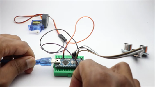
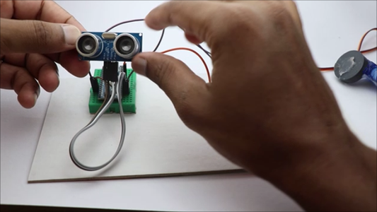
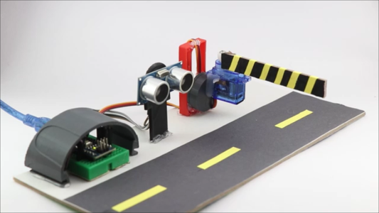
Step 3: Assembling
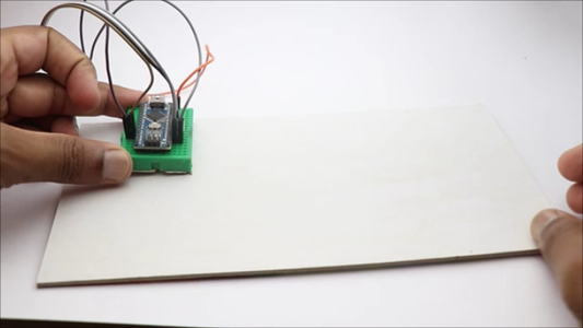
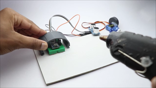
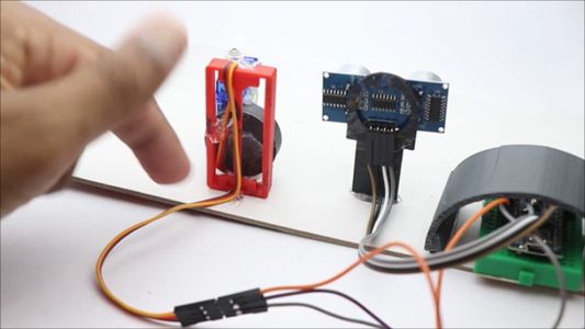
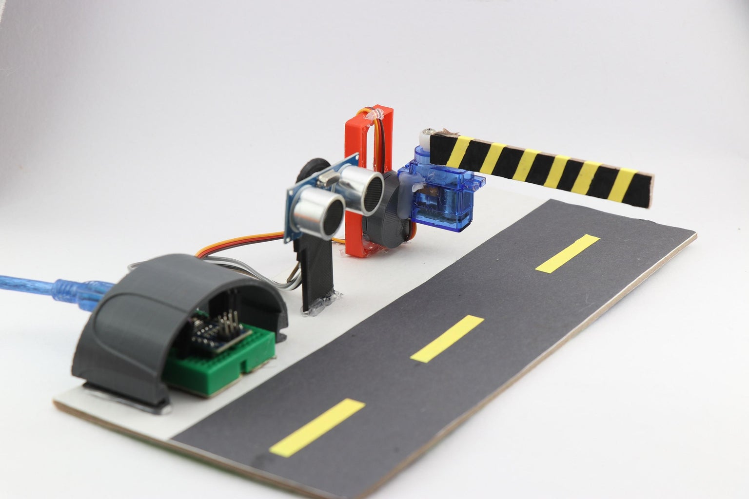
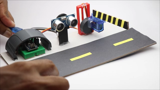
Since we have the circuit ready and working all we have to do is set all these components on a cardboard.
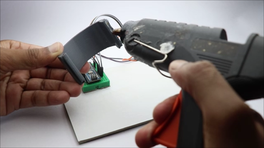
Start by placing the breadboard and nano on the cardboard, and secure them by adding a tiny amount of hot glue.
I used a thing from 3d print that looks like an arc but it will keep all the wires in place and avoid any disconnection of wires.
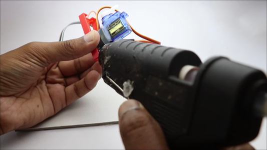
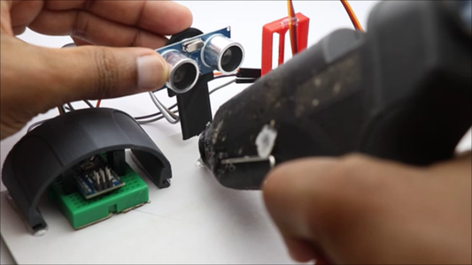
To set the servos I used some recycled parts that luckily served my purpose, you can use strips of cardboard for this purpose too.
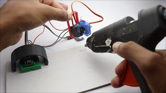
Now follow the same instructions to keep ultrasonic sensor in place.
Glue all the components in the place as you can see in the images above.
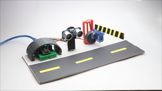
Step 4: Finishing

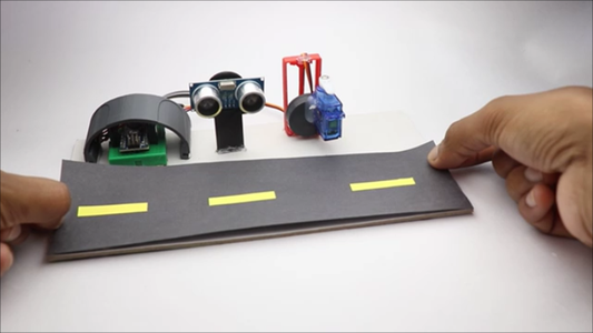

Only the last two things pending now are the roadways and the barrier
I have made the road with the help of a black sheet of paper that was cut in the form of a rectangle(due to the availability of space in the cardboard)
Stick a few small stripes of paper that resemble actual road
Use paper glue to stick this setup to the cardboard
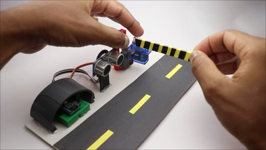
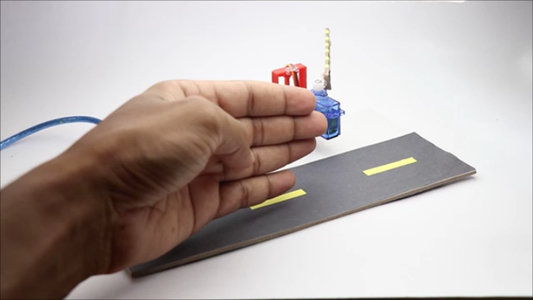
Now for the gate, you can use a strip of cardboard colored to look more like a caution gate
Use hot glue to attach this strip to the horns of the micro servo
Step 5: How It Works

As we have discussed earlier this works in a simple way
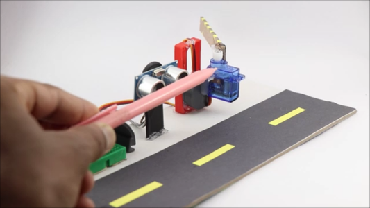
When an obstacle is detected by the ultrasonic sensor it activates the micro servo which in return opens the gates for a certain time.
After the given duration is passed the gate closes automatically eliminating the entry of others.
Why this Arduino gate system?
This Arduino gate system effectively automates the process of opening and closing the gate, eliminating the need for manual intervention.
Additionally, it provides a more convenient experience for users, as they do not have to physically interact with the gate to gain entry.
Overall, the Arduino gate system represents a fantastic application of technology, combining sensors, microcontrollers, and actuators to create a smart and efficient entry access solution.
Step 6: Working Video
You have made it till here! Now you should not miss the working video of this project, you can also use this link to watch the video https://youtu.be/9JeFP3eq0EE
Any questions are always welcome in the comments box, Thank you and have a wonderful day.


![Tim's Mechanical Spider Leg [LU9685-20CU]](https://content.instructables.com/FFB/5R4I/LVKZ6G6R/FFB5R4ILVKZ6G6R.png?auto=webp&crop=1.2%3A1&frame=1&width=306)


